background image

1U Rackmount Server

User Guide

RS500-E9 Series 

RS500-E9-PS4

RS500-E9-RS4

RS500-E9-RS4-U

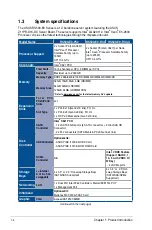
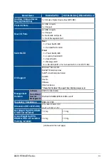
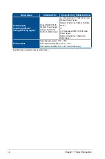
Summary of Contents for RS500-E9 Series

Page 1: ...1U Rackmount Server User Guide RS500 E9 Series RS500 E9 PS4 RS500 E9 RS4 RS500 E9 RS4 U ...

Page 2: ...tion of business and the like even if ASUS has been advised of the possibility of such damages arising from any defect or error in this manual or product Specifications and information contained in this manual are furnished for informational use only and are subject to change at any time without notice and should not be construed as a commitment by ASUS ASUS assumes no responsibility or liability ...

Page 3: ...er 2 2 2 2 Central Processing Unit CPU 2 3 2 2 1 Installing the CPU and heatsink 2 3 2 3 System memory 2 6 2 3 1 Overview 2 6 2 3 2 Memory Configurations 2 6 2 3 3 Installing a DIMM on a single clip DIMM socket 2 8 2 4 Hard disk drives 2 9 2 5 Expansion slot 2 13 2 5 1 Installing an expansion card to the riser card bracket 2 13 2 5 2 Installing an ASUS PIKE II card 2 14 2 5 3 Installing M 2 NGFF c...

Page 4: ... 5 2 5 1 2 ASUS EZ Flash Utility 5 3 5 1 3 BUPDATER utility 5 4 5 2 BIOS setup program 5 6 5 2 1 BIOS menu screen 5 7 5 2 2 Menu bar 5 7 5 2 3 Menu items 5 8 5 2 4 Submenu items 5 8 5 2 5 Navigation keys 5 8 5 2 6 General help 5 8 5 2 7 Configuration fields 5 8 5 2 8 Pop up window 5 8 5 2 9 Scroll bar 5 8 5 3 Main menu 5 9 5 3 1 System Date Day xx xx xxxx 5 9 5 3 2 System Time xx xx xx 5 9 5 4 Adv...

Page 5: ...n 5 30 5 6 2 Common RefCode Configuration 5 32 5 6 3 UPI Configuration 5 33 5 6 4 Memory Configuration 5 34 5 6 5 IIO Configuration 5 35 5 6 6 Advanced Power Management Configuration 5 36 5 7 Event Logs menu 5 38 5 7 1 Change Smbios Event Log Settings 5 38 5 7 2 View Smbios Event Log 5 39 5 8 Server Mgmt menu 5 39 5 8 1 System Event Log 5 40 5 8 2 BMC network configuration 5 40 5 8 3 View System E...

Page 6: ...a RAID set 6 13 6 3 2 Changing a Volume Type 6 15 6 3 3 Deleting a volume 6 16 6 3 4 Preferences 6 17 6 4 Intel Virtual Raid on CPU in BIOS 6 18 6 4 1 Creating a RAID set 6 19 6 4 2 Deleting a RAID set 6 21 Chapter 7 Driver Installation 7 1 RAID driver installation 7 2 7 1 1 Creating a USB flash drive with RAID drive 7 2 7 1 2 Installing the RAID controller driver 7 2 7 2 Management applications a...

Page 7: ... operating the server carefully read all the manuals included with the server package Before using the server ensure all cables are correctly connected and the power cables are not damaged If any damage is detected contact your dealer as soon as possible To avoid short circuits keep paper clips screws and staples away from connectors slots sockets and circuitry Avoid dust humidity and temperature ...

Page 8: ...ion Options This chapter describes how to install optional components into the barebone server 4 Chapter 4 Motherboard Information This chapter gives information about the motherboard that comes with the server This chapter includes the motherboard layout jumper settings and connector locations 5 Chapter 5 BIOS Setup This chapter tells how to change system settings through the BIOS Setup menus and...

Page 9: ...ly the required item or value enclosed in brackets Example At the DOS prompt type the command line format A S DANGER WARNING Information to prevent injury to yourself when trying to complete a task CAUTION Information to prevent damage to the components when trying to complete a task NOTE Tips and additional information to help you complete a task IMPORTANT Instructions that you MUST follow to com...

Page 10: ...x ...

Page 11: ...This chapter describes the general features of the chassis kit It includes sections on front panel and rear panel specifications 1 Product Introduction Chapter 1 Product Introduction ...

Page 12: ...ly RS500 E9 PS4 1 x 770W Redundant Power Supply RS500 E9 RS4 RS500 E9 RS4 U 4 x Hot swap 3 5 inch HDD Trays 1 x SAS SATA Backplane RS500 E9 PS4 RS500 E9 RS4 1 x SAS SATA NVMe Backplane RS500 E9 RS4 U 1 x PCI E Riser Card 1 x Front I O Board 6 x System Fans 40 mm x 28 mm 1 x Redundant Power Supply Power Distribution Board RS500 E9 RS4 RS500 E9 RS4 U Accessories 1 x Support DVD 1 x Bag of Screws 1 x...

Page 13: ...eam you must take note of the product s serial number containing 12 characters such as xxS0xxxxxxxx shown as the figure below With the correct serial number of the product ASUS Technical Support team members can then offer a quicker and satisfying solution to your problems 4 3 2 1 xxS0xxxxxxxx RS500 E9 Series ...

Page 14: ...RDIMM 128GB 64GB LRDIMM 3DS Refer to www asus com for the latest memory AVL update Expansion Slots T o t a l P C I PCI X PCI E Slots 2 1 Slot Type 1 x PCI E x16 Gen3 x16 link FH HL 1 x PCI E x8 Gen3 x8 link FH HL 1 x OCP 2 0 Mezzanine Gen3 x16 link Disk Controller SATA Controller Intel C621 PCH 12 x SATA 6Gb s ports 4 SATA connectors 2 mini SAS HD Connector 2 x M 2 connectors SATA 6Gb s PCI E Gen3...

Page 15: ... Switch 1 x Message LED 4 x LAN LED LED1 2 for on board LAN 3 4 for OCP LAN OS Support Windows Server 2016 RedHat Enterprise Linux SuSE Linux Enterprise Server CentOS Ubuntu VMware Citrix XenServer Please find the latest OS support from http www asus com Management Solution Software ASUS Control Center Out of Band Remote Management On Board ASMB9 iKVM for KVM over IP Regulatory Compliance BSMI CE ...

Page 16: ...g 100 240 Vac 9A 5A 50 60Hz Class I 1 1 Redundant 770W 80 PLUS Platinum Power Supply Rating 100 240 Vac 10A 5A 50 60Hz Class I or 1 1 Redundant 450W 80 PLUS Gold Power Supply Rating 100 240 Vac 5 5A 3A 50 60Hz Class I Environment Operating temperature 10 C 35 C Non operation temperature 40 C 70 C Non operation humidity 20 90 Non condensing Specifications are subject to change without notice ...

Page 17: ...rboard 4 3 2 1 Optical drive optional Asset tag hidden Rack screw Rack screw USB 3 0 ports VGA port LAN 2 LED LAN 1 LED LAN 4 LED LAN 3 LED Message LED Power button Location switch Reset button HDD LED HDD 1 HDD 2 HDD 3 HDD 4 This port is for ASUS ASMB9 iKVM controller card only RS500 E9 RS4 RS500 E9 RS4 U RS500 E9 PS4 VGA port Gigabit LAN port 1 bottom and 2 top USB 3 0 ports LAN port for iKVM OC...

Page 18: ... 2 Connects to SATA2 port 8 HDD tray 3 Connects to SATA3 port 9 HDD tray 4 Connects to SATA4 port 10 Front I O boards hidden 11 Slim type optical drive 12 Asset Tag The barebone server does not include a floppy disk drive Connect a USB floppy disk drive to any of the USB ports on the front or rear panel if you need to use a floppy disk WARNING HAZARDOUS MOVING PARTS KEEP FINGERS AND OTHER BODY PAR...

Page 19: ...D Message LED OFF ON System is normal no incoming event A hardware monitor event is indicated Location LED OFF ON Normal status Location switch is pressed Press the location switch again to turn off LAN LEDs OFF Blinking ON No LAN connection LAN is transmitting or receiving data LAN connection is present 4 3 2 1 LAN 2 LED LAN 1 LED LAN 4 LED LAN 3 LED HDD LED Power button Location switch Message L...

Page 20: ...to the SATA SAS HDD HDD Activity LED 1 7 2 LAN RJ 45 LEDs LAN port LED indications LAN port Activity Link LED Speed LED Status Description Status Description OFF No link GREEN 1 Gbps connection GREEN Linked BLINKING Data activity Dedicated Management LAN port DM_LAN1 LED indications DM LAN port Activity Link LED Speed LED Status Description Status Description OFF No link OFF 10 Mbps connection YEL...

Page 21: ...This chapter lists the hardware setup procedures that you have to perform when installing or removing system components 2 Hardware Information Chapter 2 Hardware Information ...

Page 22: ...until it is disengaged from the chassis 4 Lift the cover from the chassis 5 To reattach the rear cover reverse step 1 to 4 2 Loosen the two thumbscrews on the rear panel to release the rear cover from the chassis Thumbscrews A protection film is pre attached to the system cover before shipping Please remove the protection film before turning on the system for proper heat dissipation Front side scr...

Page 23: ... PnP cap is missing or if you see any damage to the PnP cap socket contacts motherboard components ASUS will shoulder the cost of repair only if the damage is shipment transit related The product warranty does not cover damage to the socket contacts resulting from incorrect CPU installation removal or misplacement loss incorrect removal of the PnP cap 2 2 1 Installing the CPU and heatsink To insta...

Page 24: ...hen the four screws are attached tighten them one by one in a diagonal sequence to completely secure the heatsink The heatsink screws are T30 models A torque value of 12 inch lbf is recommended 3 Align the triangle mark on the CPU with the triangle mark on the CPU Carrier A then install the CPU into the CPU Carrier until it clicks firmly into place B and then install the CPU Carrier into the heats...

Page 25: ...2 5 ASUS RS500 E9 Series 6 Reinstall the air ducts CPU1 CPU socket 1 CPU2 CPU socket 2 ...

Page 26: ...e location of the DDR4 DIMM sockets 2 3 2 Memory Configurations You may install 32GB 16GB 8GB 4GB RDIMM 64GB 32GB LRDIMM or 128GB 64GB LRDIMM 3DS into the DIMM sockets using the memory configurations in this section Always install DIMMs with the same CAS latency For optimum compatibility it is recommended that you obtain memory modules from the same vendor Start installing the DIMMs in slots A1 ...

Page 27: ... P P P P P P P P P P P P P Single CPU configuration must be installed on CPU1 DIMM A2 A1 B1 C1 D2 D1 E1 F1 1 DIMM P 2 DIMMs P P 4 DIMMs P P P P 6 DIMMs P P P P P P 8 DIMMs P P P P P P P P Dual CPU configuration You can refer to the following recommended memory population for a dual CPU configuration Single CPU configuration You can refer to the following recommended memory population for a single ...

Page 28: ...ked Retaining Clip 1 Unlock a DIMM socket by pressing the retaining clip outward 2 Align a DIMM on the socket such that the notch on the DIMM matches the DIMM slot key on the socket Unlocked retaining clip DIMM notch DIMM slot key 1 Press the retaining clip outward to unlock the DIMM 2 Remove the DIMM from the socket Removing a DIMM from a single clip DIMM socket Support the DIMM lightly with your...

Page 29: ...SAS backplane To install a 3 5 hot swap SATA SAS HDD 1 Push the spring lock to the right A then pull the tray lever outward B to release the drive tray The drive tray ejects slightly after you pull out the lever 2 Firmly hold the tray lever and pull the drive tray out of the bay 3 Place the drive tray on a flat and stable surface 4 Prepare the SATA SAS HDD and the bundled set of screws spring lock...

Page 30: ... of the bay until just a small fraction of the tray edge protrudes 7 Push the tray lever until it clicks and secures the drive tray in place The drive tray is correctly placed when its front edge aligns with the bay edge 8 Repeat steps 1 to 7 to install the other SATA SAS HDDs When installed the SATA SAS connector on the drive connects to the SATA SAS interface on the backplane ...

Page 31: ... then pull the tray lever outward B to release the drive tray The drive tray ejects slightly after you pull out the lever spring lock tray lever 2 Firmly hold the tray lever and pull the tray out of the bay 3 Place the tray on a flat and stable surface 4 Prepare the 2 5 storage device and the bundled set of screws ...

Page 32: ...he tray is correctly placed when its front edge aligns with the bay edge 8 Repeat steps 1 to 7 to install the other storage devices When installed the SATA NVMe connector on the storage device connects to the SATA NVMe interface on the backplane 6 Insert the tray and storage device assembly all the way into the depth of the bay until just a small fraction of the tray edge protrudes ...

Page 33: ...PCI Express x8 or x16 expansion cards To install a PCI Express x8 or x16 card 2 Place the riser card bracket on a flat and stable surface then remove the screw from the slot bay 1 Firmly hold the riser card bracket then pull it up to detach it from the PCI Express x24 slot on the motherboard 3 Install a PCI Express x8 or x16 card to the bracket as shown 4 Secure the card with a screw 3 4 2 1 5 Q C...

Page 34: ...oard Ensure that the golden connectors of the riser card bracket is firmly seated in place 5 2 5 2 Installing an ASUS PIKE II card You can install an ASUS PIKE II card on the provided PCI E slot onboard To install an ASUS PIKE II card 1 Firmly hold the riser card bracket then pull it up to detach it from the PCI Express x24 slot on the motherboard ...

Page 35: ...cover to the riser card bracket then remove the metal cover 3 Prepare your ASUS PIKE II card 4 Insert the expansion card into the PCI E slot Ensure that the golden fingers are totally inserted into the slot then secure the ASUS PIKE II card with the screw removed before ...

Page 36: ...er 2 Hardware Information 2 16 5 Remove the default mini SAS HD cable from the motherboard Z11PR D16 DC 6 Connect the mini SAS HD cable to connector 1 of the ASUS PIKE II card Connect to PIKE II connector 1 ...

Page 37: ...2 17 ASUS RS500 E9 Series 7 Reinstall the riser card bracket into the PCI Express x24 slot on the motherboard Ensure that the golden connectors of the riser card bracket is firmly seated in place ...

Page 38: ... install an M 2 NGFF card 2 Remove the top screw and the stand from the motherboard 3 Select an appropriate screw hole on the motherboard for your M 2 card then secure the stand to the motherboard 1 Locate the M 2 NGFF connectors on your motherboard Top screw Stand screw ...

Page 39: ...re securing it 4 Prepare the M 2 card 5 Align and insert the M 2 card into the M 2 connector on the motherboard Ensure that the golden connector of the M 2 card is inserted firmly in place and that the screw hole on the M 2 card matches the stand screw on the motherboard 6 Secure the M 2 card with the top screw ...

Page 40: ...0 2 5 4 Installing Mezzanine cards To install a Mezzanine card 1 Locate the Mezzanine card connector on your motherboard 2 Firmly hold the riser card bracket then pull it up to detach it from the PCI Express x24 slot on the motherboard ...

Page 41: ...the signal transmission end white to the AUXLED_CON header on the card AUXLED_CON1 Stand screws LAN ports LAN port slots Screw holes 5 Insert the ports of the Mezzanine card into the mounting hole on the chassis then insert the golden connector of the Mezzanine card into the MEZZPCIE1 OCP connector on the motherboard Ensure that the stand screws on the motherboard is aligned and matched to the scr...

Page 42: ...e signal cable are different in size and color for easy recognition Please refer to your exact cable 6 Secure the Mezzanine card with the four 4 bundled screws 8 Reinstall the riser card bracket into the PCI Express x24 slot on the motherboard Ensure that the golden connectors of the riser card bracket is firmly seated in place ...

Page 43: ...ivers for the expansion card Standard Interrupt assignments These IRQs are usually available for ISA or PCI devices IRQ Priority Standard function 0 1 System Timer 1 2 Keyboard Controller 2 Programmable Interrupt 3 11 Communications Port COM2 4 12 Communications Port COM1 5 13 6 14 Floppy Disk Controller 7 15 8 3 System CMOS Real Time Clock 9 4 ACPI Mode when used 10 5 IRQ Holder for PCI Steering ...

Page 44: ...cables connected to the motherboard 1 24 pin ATX power connector from power supply to motherboard 2 8 pin 12V power connector from power supply to motherboard 3 System fan connector from system fan to motherboard 4 USB connector from motherboard to front I O board 5 SATA connector system default from motherboard to backplane 6 System auxiliary panel connector from motherboard to front I O board 7 ...

Page 45: ...ects the data cables connected to the motherboard Connects an 8 pin plug from power supply RS500 E9 RS4 RS500 E9 PS4 BP4LE12G 35 RIDE Connects to the SATA SAS NMVE storage device Connects the data cables connected to the motherboard Connects an 8 pin plug from power supply Connects the data cables connected to the motherboard ...

Page 46: ...hat the system is turned off before removing any components from your system 2 8 1 System fans To uninstall the system fans 1 Disconnect the system fan cable from the fan connector on the motherboard 2 Lift the fan then set aside 3 Repeat steps 1 to 2 to uninstall the other system fans To reinstall the system fans 1 Insert the fan to the fan cage The airflow directional arrow on the fan side shoul...

Page 47: ...This chapter describes how to install the optional components and devices into the barebone server 3 Installation Options Chapter 3 Installation Options ...

Page 48: ...dditional support and stability to the server The tool less rail kit package includes 3 1 2 Installing the tool less rack rail To install the tool less rack rails into the rack 1 Secure the two fixing latches to the two sides of the server using the set of latch screws The locations of the screw holes vary with different server models Refer to your server user manual for details Fixing latches Set...

Page 49: ...ail then prepare one of the bundled rail components 1U Rail component 3 Align the rail component with the right rack rail and secure it using four 4 bundled screws 4 Follow steps 2 and 3 to secure the rail component to the left rail rack 5 Select a desired space and place the appropriate rack rail left and right on opposite positions on the rack A 1U space consists of three square mounting holes w...

Page 50: ... the mounting hole on the rack post Extend the rack rail if necessary 9 Optional Use the rail screw and rail washer that comes with the kit to secure the rack rail to the rack post 10 Perform steps 3 to 5 for the other rack rail Ensure that the installed rack rails left and right are aligned secured and stable in place 11 Lift the server chassis and insert into the rack rail Ensure that the rack r...

Page 51: ...3 5 ASUS RS500 E9 Series 3 2 Rail kit dimensions 589mm 43 6mm 900mm 43 6mm ...

Page 52: ...Chapter 3 Installation Options 3 6 ...

Page 53: ...This chapter includes the motherboard layout and brief descriptions of the jumpers and internal connectors 4 Motherboard Information Chapter 4 Motherboard Information ...

Page 54: ...Chapter 4 Motherboard Information 4 2 4 1 Motherboard layout ...

Page 55: ...sensor cable connector 3 pin TR1 4 24 16 Serial port connector 10 1 pin COM1 4 16 17 Micro SD card slot MSD1 4 23 18 DMLAN setting 3 pin DM_IP_SEL1 4 7 19 LANNCSI setting 3 pin LANNCSI_SEL1 4 8 20 BMC Setting 3 pin BMC_EN1 4 7 21 DDR4 thermal event setting 3 pin DIMMTRIP1 2 4 6 22 VGA controller setting 3 pin VGA_SW1 4 5 23 PCH_MFG1 setting 3 pin PCH_MFG1 4 8 24 ME firmware force recovery setting ...

Page 56: ... computer and unplug the power cord 2 Move the jumper cap from the default pins 1 2 to pins 2 3 Keep the cap on pins 2 3 for about 5 to 10 seconds then move the cap back to pins 1 2 3 Plug the power cord and turn ON the computer 4 Hold down the Del key during the boot process and enter BIOS setup to re enter data DO NOT remove the cap on CLRTC jumper default position except when clearing the RTC R...

Page 57: ...is jumper allows you to enable or disable the onboard VGA controller Set to pins 1 2 to activate the VGA feature 3 LAN controller setting 3 pin LAN_SW1 This jumper allows you to enable or disable the onboard LAN_SW1 Set to pins 1 2 to activate the Gigabit LAN feature ...

Page 58: ...very setting 3 pin ME_RCVR1 This jumper allows you to force Intel Management Engine ME boot from recovery mode when ME becomes corrupted 5 DDR4 thermal event setting 3 pin DIMMTRIP1 2 These jumpers allow you to enable or disable DDR4 DIMM thermal sensing event pin ...

Page 59: ...is jumper allows you to enable or disable the Baseboard Management Controller ASMB9 7 DMLAN setting 3 pin DM_IP_SEL1 This jumper allows you to select the DMLAN setting Set to pins 2 3 to force the DMLAN IP to static mode IP 10 10 10 10 submask 255 255 255 0 ...

Page 60: ... Motherboard Information 4 8 8 PCH_MFG1 setting 3 pin PCH_MFG1 This jumper allows you to update the BIOS ME block 9 LANNCSI setting 3 pin LANNCSI_SEL1 This jumper allows you to select which LAN NCSI to function ...

Page 61: ...tting 3 pin SMART_PSU1 This jumper allows you to enable or disable the Smart Ride Through SmaRT function This feature is enabled by default Set to pins 2 3 to disable it When enabled SmaRT allows uninterrupted operation of the system during an AC loss event ...

Page 62: ...m is ON in sleep mode or in soft off mode This is a reminder that you should shut down the system and unplug the power cable before removing or plugging in any motherboard component The illustration below shows the location of the onboard LED 2 BMC LED BMCLED1 The BMC LED lights up to indicate that the on board BMC is functional This LED functions only when you enable ASUS ASMB9 ...

Page 63: ...he server is pressed or when triggered by a system management software The Location LED helps visually locate and quickly identify the server in error on a server rack 4 CATT LED CATTERR_LED1 The CATT LED indicates that the system has experienced a fatal or catastrophic error and cannot continue to operate ...

Page 64: ...en there is a BMC event log is generated 6 Hard disk activity LED HDDLED1 This LED is for the storage devices connected to the onboard SATA or SATA SAS add on card The read or write activities of any device connected to the onboard SATA or SATA SAS add on card causes the rear panel LED to light up ...

Page 65: ...ther SMBus devices using the SMBus interface This connector functions only when you enable ASUS ASMB9 4 4 Internal connectors 1 Serial ATA 6 0Gb s connectors 7 pin SSATA1 4 Supported by the Intel C621 chipset these connectors are for the Serial ATA signal cables for Serial ATA hard disk drives SATA 1 connector is used for the optical drive by default The actual data transfer rate depends on the sp...

Page 66: ...al Bus Type A port is available for connecting USB 2 0 devices These USB connectors comply with USB 2 0 specification that supports up to 480 Mbps connection speed 4 USB 3 0 connector 20 1 pin USB3_34 4 pin Type A USB3_5 The 20 1 pin connector allows you to connect a USB 3 0 module for additional USB 3 0 front or rear panel ports The 4 pin USB Universal Serial Bus Type A port is available for conn...

Page 67: ...1 7 REAR_FAN1 2 The fan connectors support cooling fans Connect the fan cables to the fan connectors on the motherboard ensuring that the black wire of each cable matches the ground pin of the connector DO NOT forget to connect the fan cables to the fan connectors Insufficient air flow inside the system may damage the motherboard components These are not jumpers DO NOT place jumper caps on the fan...

Page 68: ...onnectors then install the module to a slot opening at the back of the system chassis 8 Trusted Platform Module connector 20 1 pin TPM1 This connector supports a Trusted Platform Module TPM system which can securely store keys digital certificates passwords and data A TPM system also helps enhance network security protects digital identities and ensures platform integrity ...

Page 69: ...he connectors completely fit DO NOT forget to connect the 24 pin and the 8 pin power plugs otherwise the system will not boot up Use of a power supply unit PSU with a higher power output is recommended when configuring a system with more power consuming devices The system may become unstable or may not boot up if the power is inadequate This motherboard supports ATX2 0 PSU or later version Ensure ...

Page 70: ...SPEAKER This 4 pin connector is for the chassis mounted system warning speaker The speaker allows you to hear system beeps and warnings 4 Hard disk drive activity LED 2 pin HDLED This 2 pin connector is for the HDD Activity LED Connect the HDD Activity LED cable to this connector The LED lights up or flashes when data is read from or written to the HDD 5 ATX power button soft off button 2 pin PWRS...

Page 71: ...the Gigabit LAN activity LEDs on the front panel 3 Locator LED 2 pin LOCATORLED1 LOCATORLED2 These leads are for the locator LED1 and LED2 on the front panel Connect the Locator LED cables to these 2 pin connector The LEDs will light up when the Locator button is pressed 4 Locator Button Switch 2 pin LOCATORBTN These leads are for the locator button on the front panel This button queries the state...

Page 72: ... VGA High Dynamic Range interface 13 Hard disk activity LED connector 4 pin HDLED1 This LED connector is for the storage add on card cable connected to the SATA or SAS add on card The read or write activities of any device connected to the SATA or SAS add on card causes the front panel LED to light up ...

Page 73: ...ntrusion sensor or microswitch When you remove any chassis component the sensor triggers and sends a high level signal to these leads to record a chassis intrusion event The default setting is short CASEOPEN and GND pin by jumper cap to disable the function 15 OCUPCIE connectors OCUPCIE1 4 Connects the PCIE signal to the NVME port on the backplane ...

Page 74: ...tors allow you to install M 2 devices The M 2 NGFF device is purchased separately This connector supports type 2242 2260 2280 22110 devices on both PCI E and SATA interface 17 Mezzanine PCIE card connectors MEZZPCIE1 2 The MEZZPCIE1 2 connector supports Open Compute Project OCP cards ...

Page 75: ...3 00 SDXC Disconnect all power including redundant PSUs from the existing system before you add or remove a Memory Card then reboot the system to access the Memory Card This Micro SD card slot functions only when you enable ASUS ASMB9 Some memory cards may not be compatible with your motherboard Ensure that you use only compatible memory cards to prevent loss of data damage to your device or memor...

Page 76: ...hat is used for monitoring temperature Connect the thermal sensor cable to the connector and place its probe to the device that you want to monitor 21 Mini SAS HD connectors ISATA1 2 This motherboard comes with mini Serial Attached SCSI SAS HD connectors the storage technology that supports Serial ATA Each connector supports up to four devices ...

Page 77: ... VPP_I2C1 connector 10 1 pin VPP_I2C1 This connector is used for the Intel VMD function and sensor readings 23 VROC_KEY connector 4 pin VROC_KEY1 This connector allows you to connect a KEY module to support Intel VMD RAID function ...

Page 78: ...26 24 System Management Bus SMBUS connector 5 1 pin SMBUS1 This connectors controls the system and power management related tasks This connector processes the messages to and from devices rather than tripping the individual control lines ...

Page 79: ...5 BIOS Setup This chapter tells how to change the system settings through the BIOS Setup menus Detailed descriptions of the BIOS parameters are also provided Chapter 5 BIOS Setup ...

Page 80: ...atically recover the BIOS It resets the system when the BIOS recovery finished DO NOT shut down or reset the system while recovering the BIOS Doing so would cause system boot failure The recovered BIOS may not be the latest BIOS version for this motherboard Visit the ASUS website at www asus com to download the latest BIOS file Save a copy of the original motherboard BIOS file to a bootable USB fl...

Page 81: ...s utility download the latest BIOS from the ASUS website at www asus com To update the BIOS using EZ Flash Utility 1 Insert the USB flash disk that contains the latest BIOS file into the USB port 2 Enter the BIOS setup program Go to the Tool menu then select ASUS EZ Flash Utility Press Enter ASUS Tek EzFlash Utility Up Down Left Right Switch Enter Choose q Exit FS0 System Volume Information DIR Wi...

Page 82: ...y The actual BIOS screen displays may not be the same as shown The BUPDATER utility allows you to update the BIOS file in the DOS environment using a bootable USB flash disk drive with the updated BIOS file Updating the BIOS file To update the BIOS file using the BUPDATER utility 1 Visit the ASUS website at www asus com and download the latest BIOS file for the motherboard Save the BIOS file to a ...

Page 83: ... returns to the DOS prompt after the BIOS update process is completed Reboot the system from the hard disk drive The BIOS update is finished Please restart your system C Current Platform Platform Z11PR D16 DC Version 0201 Build date 12 04 2018 New Platform Platform Z11PR D16 DC Version 0207 Build date 01 05 2018 ASUS Tek EzFlash Utility Start Programming Flash DO NOT SHUTDOWN THE SYSTEM Write 75 ...

Page 84: ...un this program Press Del during the Power On Self Test POST to enter the Setup utility otherwise POST continues with its test routines If you wish to enter Setup after POST restart the system by pressing Ctrl Alt Delete or by pressing the reset button on the system chassis You can also restart by turning the system off and then back on Do this last option only if the first two failed The Setup pr...

Page 85: ...nfiguration For changing the platform settings Socket Configuration For changing the socket settings Event Logs For changing the event log settings Server Mgmt For changing the server mgmt settings Security For changing the security settings Boot For changing the system boot configuration Tool For configuring options for special functions Save Exit For selecting the save exit options To select an ...

Page 86: ...n the menu and change the settings 5 2 6 General help At the top right corner of the menu screen is a brief description of the selected item 5 2 7 Configuration fields These fields show the values for the menu items If an item is user configurable you can change the value of the field opposite the item You cannot select an item that is not user configurable A configurable field is enclosed in brac...

Page 87: ...nu screen appears The Main menu provides you an overview of the basic system information and allows you to set the system date time language and security settings 5 3 1 System Date Day xx xx xxxx Allows you to set the system date 5 3 2 System Time xx xx xx Allows you to set the system time ...

Page 88: ...1 Trusted Computing Configuration Security Device Support Enabled Allows you to enable or disable the BIOS support for security device Configuration options Disabled Enabled Optimized Performance Settings Default This option allows you to select a recommended BIOS setting to optimize performance Asus Turbo Ratio Lock ATRL Disabled Allows you to keep the processor operating at the turbo highest fre...

Page 89: ... 5 4 2 ACPI Settings Enable ACPI Auto Configuration Disabled Allows you to enable or disable the BIOS ACPI Auto Configuration Configuration options Disabled Enabled Enable Hibernation Enabled Allows you to enable or disable the ability of the system to hibernate OS S4 Sleep State Configuration options Disabled Enabled This option may be not be effective with some OS ...

Page 90: ...nly when you set Serial Port to Enabled Change Settings Auto Allows you to choose the setting for Super IO device Configuration options Auto IO 3F8h IRQ 4 IO 3F8h IRQ 3 4 5 6 7 9 10 11 12 IO 2F8h IRQ 3 4 5 6 7 9 10 11 12 IO 3E8h IRQ 3 4 5 6 7 9 10 11 12 IO 2E8h IRQ 3 4 5 6 7 9 10 11 12 5 4 5 Serial Port Console Redirection COM1 COM2 Console Redirection Disabled Allows you to enable or disable the ...

Page 91: ...har set Bits per second 57600 Selects serial port transmission speed The speed must be matched on the other side Long or noisy lines may require lower speeds Configuration options 9600 19200 38400 57600 115200 Data Bits 8 Configuration options 7 8 Parity None A parity bit can be sent with the data bits to detect some transmission errors Mark and Space parity do not allow for error detection None N...

Page 92: ... Legacy OS Redirection Resolution 80x24 This allows you to set the number of rows and columns supported on the Legacy OS Configuration options 80x24 80x25 Putty Keypad VT100 This allows you to select the FunctionKey and Keypad on Putty Configuration options VT100 LINUX XTERMR6 SCO ESCN VT400 Redirection After BIOS POST Always Enable This setting allows you to specify if Bootloader is selected than...

Page 93: ...t the terminal type for out of band management Configuration options VT100 VT100 VT UTF8 ANSI Bits per second 115200 Allows you to set the serial port transmission speed Configuration options 9600 19200 57600 115200 Flow Control None Allows you to set the flow control to prevent data loss from buffer overflow Configuration options None Hardware RTS CTS Software Xon Xoff Intel X722 LAN Enable Enabl...

Page 94: ...tate the system goes into either off or on state whatever the system state was before the AC power loss Configuration options Power Off Power On Last State Power On By PCIE Disabled Disabled Disables the PCIE devices to generate a wake event Enabled Enables the PCIE devices to generate a wake event Power On By RTC Disabled Disabled Disables RTC to generate a wake event Enabled When set to Enabled ...

Page 95: ...ded in above 4G address space only if system supports 64 bit PCI decoding Configuration options Auto Above 4G SR IOV Support Enabled This option enables or disables SIngle Root IO Virtualization Support if the system has SRIOV capable PCIe devices Configuration options Disabled Enabled PCI Express Settings PCI Express Device Register Settings Relaxed Ordering Enabled This option allows you to enab...

Page 96: ...ion allows you to set the ASPM level Force L0s Force all links to L0s State Auto BIOS auto configure Disabled Disables ASPM Enabling ASPM may cause some PCI E devices to fail Extended Synch Disabled This option allows the generation of Extended Synchronization patterns when set to Enabled Configuration options Disabled Enabled Link Training Retry 5 This option allows you to set the number of Retry...

Page 97: ...on initiates Atomic0p Requests only if Bus Master Enable bit is in the Command Register Set Configuration options Disabled Enabled Atomic0p Egress Blocking Disabled If supported by hardware and set to Enabled outbound Atomic0p Requests via Egress Ports will be blocked Configuration options Disabled Enabled IDO Request Enable Disabled If supported by hardware and set to Enabled this permits setting...

Page 98: ...ill force LTSSM to send SKP Ordered Sets between sequences when sending Compliance Pattern or Modified Compliance Pattern Configuration options Disabled Enabled Hardware Autonomous Width Enabled If supported by hardware and set to Disabled this will disable the hardware s ability to change link width except for width size reduction for the purpose of correcting unstable link operation Configuratio...

Page 99: ... Ipv4 HTTP Boot Support If disabled Ipv4 PXE boot option will not be created Configuration options Disable Enable Ipv6 PXE Support Disabled Enables or disables the Ipv6 PXE Boot Support If disabled Ipv6 PXE boot option will not be created Configuration options Disable Enable Ipv6 HTTP Support Disabled Enables or disables the Ipv6 HTTP Boot Support If disabled Ipv6 PXE boot option will not be creat...

Page 100: ...ages Force BIOS This allows you to set the display mode for option ROM Configuration options Force BIOS Keep Current INT19 Trap Response Immediate This option allows you to control the BIOS reaction on INT19 trapping by Option ROM Immediate Execute the trap right away Postponed Execute the trap during legacy boot Auto Allow the system to determine automatically Boot Option filter Legacy only This ...

Page 101: ...cted the legacy USB support is disabled USB Mass Storage Driver Support Enabled Allows you to enable or disable the USB Mass Storage driver support Configuration options Disabled Enabled Mass Storage Devices Allows you to select the mass storage device emulation type for devices connected Configuration options Auto Floppy Forced FDD Hard Disk CD ROM 5 4 11 NVMe Configuration You may view the NVMe ...

Page 102: ...nfigure the iSCSi parameters 5 5 Platform Configuration menu The IntelRCSetup menu items allow you to change the platform settings Take caution when changing the settings of the Platform Configuration menu items Incorrect field values can cause the system to malfunction ...

Page 103: ...Enabled in S4 and S5 GP27 Wake From DeepSx Disabled Allows you to enable or disable GP27 Wake From DeepSx Configuration options Disabled Enabled PCI Express Configuration PCI E ASPM Support Global L1 Only Allows you to select ASPM support for all downstream devices Configuration options Per individual port L1 Only PCH DMI ASPM Platform POR Allows you to configure the PCH DMI ASPM Configuration opt...

Page 104: ...abled Enabled PCH sSATA Configuration sSATA Controller Enabled Allows you to enable or disable the sSATA Controller Configuration options Disabled Enabled The following item appears only when you set sSATA Controller to Enabled Configure sSATA as AHCI Allows you to identify the SATA port connected to Solid State Drive or Hard Disk Drive Configuration options AHCI RAID Support Aggressive Link Power...

Page 105: ...bled Allows you to enable or disable each of the USB physical connectors Once a connector is disabled any USB devices plugged into the connector will not be detected by BIOS or OS Configuration options Disabled Enabled The following items appear only when the USB Per Connector Disable is set to Enabled USB_1 9 Enabled Configuration options Disabled Enabled USB3_1 5 Enabled Configuration options Di...

Page 106: ...sable PMTT ACPI Table for DDR4 only Configuration options Disabled Enabled 5 5 3 Server ME Configuration Displays the Server ME Technology parameters on your system To quickly go to the last item of the second page press the Page Down button Press the Page Up button to go back to the first item in the first page Navigate to the second page of the screen to see the rest of items in this menu by pre...

Page 107: ...nology parameters on your system System Errors Enabled This item allows you to enable or disable System Errors Configuration options Disabled Enabled Whea Settings Whea Support Enabled This item allows you to enable or disable the WHEA support Configuration options Disabled Enabled ...

Page 108: ...page Navigate to the second page of the screen to see the rest of items in this menu by pressing the Up or Down arrow keys Per Socket Configuration CPU Socket 1 2 Configuration CPU Core Disable Bitmap Hex 0 This item allows you to enable or disable the cores on the CPU Hyper threading ALL Enabled This item allows a hyper threading processor to appear as two logical processors allowing the operatin...

Page 109: ...isabled Enabled Adjacent Cache Prefetch Enabled This Item allows you to turn on off prefetching of adjacent cache lines Configuration options Disabled Enabled DCU Streamer Prefetcher Enabled This Item allows you to enable or disable prefetcher of next L1 data line Configuration options Disabled Enabled DCU IP Prefetcher Enabled This Item allows you to enable or disable prefetch of next L1 line bas...

Page 110: ...MMIO High Base Configuration options 1T 4T 16T 24T 40T 56T MMIO High Granularity Size 256G This item allows you to select the MMIO High Granularity Size Configuration options 1G 4G 16G 64G 256G 1024G Numa Enabled This item enables or disables the Non uniform Memory Access NUMA Configuration options Disabled Enabled ...

Page 111: ...ons Auto 9 6 GB s 10 4 GB s Use Per Link Setting Link L0p Enable Auto Configuration options Disabled Enabled Auto Link L1 Enable Auto Configuration options Disabled Enabled Auto Directory Mode Enable Enabled Configuration options Disabled Enabled SNC Disabled Configuration options Disabled Enabled Auto KTI Prefetch Enabled Configuration options Disabled Enabled Local Remote Threshold Auto Configur...

Page 112: ...ry Topology Displays memory topology with DIMM population information Page Policy Allows you to configure Page Policy settings Page Policy Auto Configuration options Auto Closed Adaptive Memory Map IMC Interleaving Auto Select different IMC interleaving setting Configuration options Auto 1 way Interleave 2 way Interleave Channel Interleaving Auto Select different channel interleaving setting Confi...

Page 113: ...mory Rank Sparing Disabled Allows you to enable or disable Memory Rank Sparing Configuration options Disabled Enabled Patrol Scrub Enabled Allows you to enable or disable Patrol Scrub Configuration options Disabled Enabled Socket1 2 Configuration This option allows you to change the settings related to the PCI Express Ports Intel VT for Directed I O VT d Intel VT for Directed I O VT d Enabled Allo...

Page 114: ...M State Control Hardware P States Native Mode Allows you to switch between Hardware P States mode Configuration options Disabled Native Mode Out of Band Mode Native Mode with no Legacy Support CPU C State Control Autonomous Core C State Disabled Allows you to enable or disable Autonomous Core C State Report Configuration options Disabled Enabled CPU C6 Report Auto Allows you to select CPU C6 Repor...

Page 115: ...only when you set Power Performance Tuning to OS Controls EPB PECI PCS EPB OS Controls EPB This option controls whether PECI has control over EPB Configuration options OS Controls EPB PECI Controls EPB using PCS The following item appears only when you set Power Performance Tuning to BIOS Controls EPB ENERGY_PERF_BIAS_CFG Mode Balanced Performance Configuration options Performance Balanced Perform...

Page 116: ...ons 0 99 Enabling Disabling Options Smbios Event Log Enabled Change this to enable or disable all features of Smbios Event Logging during boot Configuration options Disabled Enabled Erasing Settings Erase Event Log No Choose options for erasing Smbios Event Log Erasing is done prior to any logging activation during reset Configuration options No Yes Next reset Yes Every reset 5 7 Event Logs menu 5...

Page 117: ...nfiguration options Disabled Enabled The following items are configurable only when the OS Watchdog Timer is set to Enabled OS Wtd Timer Timeout 10 minutes Allows you to configure the length for the OS Boot Watchdog Timer Configuration options 5 minutes 10 minutes 15 minutes 20 minutes OS Wtd Timer Policy Reset This item allows you to configure the how the system should respond if the OS Boot Watc...

Page 118: ...he second page of the screen to see the rest of items in this menu by pressing the Up or Down arrow keys 5 8 1 System Event Log Allows you to change the SEL event log configuration All values changed here do not take effect until computer is restarted Erase SEL No Allows you to choose options for erasing SEL Configuration options No Yes On next reset Yes On every reset When SEL is Full Do Nothing ...

Page 119: ...namicBmcNonDhcp IPV6 DM_LAN1 Shared LAN IPV6 Support Enabled Allows you to enable or disable LAN1 IPV6 Support Configuration options Disabled Enabled Config Address source Previous State This item allows you to configure LAN channel parameters statistically or dynamically by BIOS or BMC Unspecified option will not modify any BMC network parameters during BIOS phase Configuration options Previous S...

Page 120: ...rom the Create New Password box key in a password then press Enter 3 Confirm the password when prompted To change an administrator password 1 Select the Administrator Password item and press Enter 2 From the Enter Current Password box key in the current password then press Enter 3 From the Create New Password box key in a new password then press Enter 4 Confirm the password when prompted To clear ...

Page 121: ...mpted To change a user password 1 Select the User Password item and press Enter 2 From the Enter Current Password box key in the current password then press Enter 3 From the Create New Password box key in a new password then press Enter 4 Confirm the password when prompted To clear a user password 1 Select the Clear User Password item and press Enter 2 Select Yes from the Warning message window th...

Page 122: ... mode with platform Key PK enrolled and the CSM function is disabled Configuration options Disabled Enabled Secure Boot Customization Custom Allows you to set the Secure Boot selector Configuration options Custom Standard Restore Factory keys This item will the force system to User mode This allows you to configure NVRAM to contain OEM defined factory default Secure Boot keys Reset to Setup Mode T...

Page 123: ...ou to delete the NVRAM content of all the UEFI Secure Boot key databases Export Secure Boot variables This item will copy the NVRAM content of the Secure Boot variables to a file system device Enroll Efi Image This item will allow the image to run in Secure Boot mode Device Guard Ready Remove UEFI CA from DB Remove Microsoft UEFI CA from Secure Boot DB Restore DB defaults Restore DB variable to fa...

Page 124: ...sabled POST Report 5 sec Allows you to set the desired POST Report waiting time from 1 to 10 seconds Configuration options 1 sec 10 sec Until Press ESC Boot Option Priorities These items specify the boot device priority sequence from the available devices The number of device items that appears on the screen depends on the number of devices installed in the system To select the boot device during ...

Page 125: ... you press Enter Refer to the ASUS EzFlash Utility section for details 5 12 Save Exit menu The Exit menu items allow you to save or discard your changes to the BIOS items Discard Changes and Exit Exit System setup without saving any changes Save Changes and Reset Exit System setup after saving the changes Restore Defaults Restore load default values for all the setup options Pressing Esc does not ...

Page 126: ...at appears on the screen depends on the number of devices installed in the system Click an item to start booting from the selected device Launch EFI Shell from filesystem device This item allows you to attempt to launch the EFI Shell application shellx64 efi from one of the available filesystem devices ...

Page 127: ...6 RAID Configuration This chapter provides instructions for setting up creating and configuring RAID sets using the available utilities Chapter 6 RAID Configuration ...

Page 128: ...ve for this setup The new drive must be of the same size or larger than the existing drive RAID 10 is data striping and data mirroring combined without parity redundancy data having to be calculated and written With the RAID 10 configuration you get all the benefits of both RAID 0 and RAID 1 configurations Use four new hard disk drives or use an existing drive and three new drives for this setup R...

Page 129: ...S Setup Refer to Chapter 4 for details on entering and navigating through the BIOS Setup 6 1 2 Installing hard disk drives The motherboard supports Serial ATA for RAID set configuration For optimal performance install identical drives of the same model and capacity when creating a disk array To install the SATA hard disks for RAID configuration 1 Install the SATA hard disks into the drive bays fol...

Page 130: ...ology enterprise SATA Option ROM utility 1 Turn on the system 2 During POST press Ctrl I to display the utility main menu Before you proceed ensure that you have installed the Serial ATA hard disk drives and have set the correct SATA mode in the BIOS setup ESC Exit ENTER Select Menu Select Intel R Rapid Storage Technology enterprise SATA Option ROM 3 6 0 1023 Copyright C 2003 12 Intel Corporation ...

Page 131: ...you are done ESC Previous Menu ENTER Select Change Intel R Rapid Storage Technology enterprise SATA Option ROM 3 6 0 1023 Copyright C 2003 12 Intel Corporation All Rights Reserved CREATE VOLUME MENU HELP Name RAID Level Disks Strip Size Capacity Syne Create Volume Enter a unique volume name that has no special characters and is 16 characters or less Volume0 RAID0 Strips Select Disks 128KB 0 0 GB N...

Page 132: ...gher stripe size for multimedia computer systems used mainly for audio and video editing 7 In the Capacity field item key in the RAID volume capacity that you want to use and press Enter The default value field indicates the maximum allowed capacity 8 Press Enter to start creating the RAID volume 9 From the following warning message press Y to create the RAID volume and return to the main menu or ...

Page 133: ...rn to the utility main menu or press N to return to the DELETE VOLUME menu ESC Previous Menu Select Intel R Rapid Storage Technology enterprise SATA Option ROM 3 6 0 1023 Copyright C 2003 12 Intel Corporation All Rights Reserved DELETE VOLUME MENU HELP Deleting a volume will reset the disks to non RAID WARNING ALL DISK DATA WILL BE DELETED This does not apply to Recovery volumes DEL Delete Volume ...

Page 134: ...ace A small triangle before the Port number marks the selected drive Press Enter when you are done 3 Press Y in the confirmation window to reset the drive s or press N to return to the utility main menu Port Drive Model Serial Size Status 0 ST3300656SS HWAS0000991753TR 279 3GB Member Disk 1 ST3300656SS 37VN00009846RAJ1 279 3GB Member Disk Select the disks that should be reset Resetting RAID disk w...

Page 135: ...TA Hard Disk available the utility will prompt you to rebuild the RAID Press the up down arrow keys to select the destination disk then Press Enter to start the rebuilding process or press ESC to exit 6 2 4 Exiting the Intel Rapid Storage Technology enterprise SATA Option ROM utility To exit the utility 1 From the utility main menu select 4 Exit then press Enter 2 Press Y to exit or press N to ret...

Page 136: ...ded during POST You may replace the disk drive and rebuild the RAID array To rebuild the RAID with a new hard disk 1 Remove the failed SATA hard disk and install a new SATA hard disk of the same specification into the same SATA Port Select a destination disk with the same size as the original hard disk 2 Reboot the system then follow the steps in section Rebuilding the RAID with other non RAID dis...

Page 137: ...ray in the BIOS Set at least one of the arrays bootable to boot from the hard disk 1 Reboot the system and press Del to enter the BIOS setup utility during POST 2 Go to the Boot menu and select the boot option priority 3 Use up down arrow keys to select the boot priority and press Enter See the Boot menu section of Chapter 4 for more details 4 From the Exit menu select Save Changes Exit then press...

Page 138: ...on the system and go to the windows desktop 2 Click the Intel Rapid Storage Technology enterprise icon to display the main menu Your storage system is configured for data protection increased performance and optimal data storage capacity You can create additional volumes to further optimize your storage system To enter the Intel Rapid Storage Technology enterprise utility under Windows operating s...

Page 139: ...lume type 2 Click Next 3 Enter a name for the RAID set then select the array disks 4 Select Volume Size tab you can drag the bar to decide the volume size 5 Click Next If you do not want to keep the data on one of the selected disks select NO when prompted If you want to Enable volume write back cache or Initialize volume click Advanced ...

Page 140: ... number and size of the disks You can continue using other applications during this time 7 Wait until the process is completed then click OK when prompted You still need to partition your new volume using Windows Disk Management before adding any data The RAID set is displayed in the Volumes list and you can change the settings in Volume Properties ...

Page 141: ...pe size for server systems and a higher stripe size for multimedia computer systems used mainly for audio and video editing 3 You can change the Name Select the new volume type and Select additional disks to include in the new volume if needed 4 Select the Data stripe size for the RAID array for RAID 0 10 and 5 only and click OK The available stripe size values range from 4 KB to 128 KB The follow...

Page 142: ...that you back up all your important data from your hard drives To delete a volume 1 From the utility main menu select the volume exp Volume_0000 in Volumes field you want to delete 3 Click Yes to delete the volume and return to the utility main menu or click No to return to the main menu 2 Select Delete volume in Volume Properties field The following screen appears ...

Page 143: ...rences Allow you to set to show the notification area icon and show system information warning or errors here E Mail Preferences Allow you to set to sent e mail of the following events Storage system information Storage system warnings Storage system errors ...

Page 144: ...location of the VROC_KEY1 connector To enter the Intel Virtual Raid on CPU in BIOS 1 Enter the BIOS Setup during POST 2 Go to the Advanced menu Intel R Virtual Raid on CPU All Intel VMD Controllers then press Enter to display the Intel Virtual Raid on CPU menu Refer to Chapter 4 for details on entering and navigating through the BIOS Setup Due to chipset limitation when SATA ports are set to RAID ...

Page 145: ...ed over VMD Controllers item is selected press Enter and select X to enable this function 5 Under Select Disks press Enter and select X for the disks you want to include in the RAID set 6 When the Strip Size item is selected press Enter to select strip size for the RAID array for RAID 0 10 and 5 only and then press Enter The available strip size values range from 4 KB to 128 KB The following are t...

Page 146: ...is selected enter the RAID volume capacity that you want and press Enter The default value indicates the maximum allowed capacity 8 When the Create Volume item is selected press Enter to create the RAID volume and return to the Intel Rapid Storage Technology menu ...

Page 147: ...el Virtual Raid on CPU menu or select No to cancel 6 4 2 Deleting a RAID set Be cautious when deleting a RAID set You will lose all data on the hard disk drives when you delete a RAID set To delete a RAID set 1 From the Intel Virtual Raid on CPU menu select the RAID volume you want to delete and press Enter The following screen appears ...

Page 148: ...6 22 Chapter 6 RAID Configuration ...

Page 149: ... Driver Installation This chapter provides the instructions for installing the necessary drivers for different system components in both Linux and Windows Operating Systems Chapter 7 Driver Installation ...

Page 150: ...the independent hard disk drive or bootable array This part provides the instructions on how to install the RAID controller drivers during OS installation 7 1 1 Creating a USB flash drive with RAID drive When installing Windows Server OS you can load the RAID driver from a USB flash drive You can create a USB flash drive with RAID driver in Windows by copying the files from the support DVD to the ...

Page 151: ... one optical drive installed in your system eject the Windows OS installation disc and replace with the motherboard Support DVD into the optical drive Or you may connect a USB flash drive containing the RAID controller driver Click Browse to continue 5 Locate the driver in the corresponding folder of the Support DVD or USB flash drive and then click OK to continue 6 Select the RAID controller driv...

Page 152: ...ing the RAID driver Replace the motherboard Support DVD with the Windows Server installation disc Remove the USB flash drive Select the drive to install Windows and click Next 8 Setup then proceeds with the OS installation Follow the onscreen instructions to continue ...

Page 153: ... management applications and utilities that you can install to maximize the features of your motherboard When you place the support DVD into the optical drive the DVD automatically displays the main screen if Autorun is enabled in your computer By default the Drivers tab is displayed If Autorun is NOT enabled in your computer browse the contents of the support DVD to locate the file Setup exe Doub...

Page 154: ... the computer and then log on with Administrator privileges 2 Insert the support DVD into the optical drive The support DVD automatically displays the Driver menu if Autorun is enabled in your computer If Autorun is NOT enabled in your computer browse the contents of the support DVD to locate the file Setup exe Double click the Setup exe to run the support DVD 3 Check the drivers that you would li...

Page 155: ...7 7 ASUS RS500 E9 Series 5 Follow the onscreen instructions to complete the installation ...

Page 156: ...7 8 Chapter 7 Driver Installation ...

Page 157: ...Appendix Appendix ...

Page 158: ...Z11PR D16 DC block diagram ...

Page 159: ...rror 55 Memory not installed 56 Invalid CPU type or Speed 57 CPU mismatch 58 CPU self test failed or possible CPU cache error 59 CPU micro code is not found or micro code update is failed 5A Internal CPU error 5B Reset PPI is not available 5C 5F Reserved for future AMI error codes E0 S3 Resume is stared S3 Resume PPI is called by the DXE IPL E1 S3 Boot Script execution E2 Video repost E3 OS S3 wak...

Page 160: ...9 CSM initialization 7A 7F Reserved for future AMI DXE codes 90 Boot Device Selection BDS phase is started 91 Driver connecting is started 92 PCI Bus initialization is started 93 PCI Bus Hot Plug Controller Initialization 94 PCI Bus Enumeration 95 PCI Bus Request Resources 96 PCI Bus Assign Resources 97 Console Output devices connect 98 Console input devices connect 99 Super IO Initialization 9A U...

Page 161: ...lable D4 PCI resource allocation error Out of Resources D5 No Space for Legacy Option ROM D6 No Console Output Devices are found D7 No Console Input Devices are found D8 Invalid password D9 Error loading Boot Option LoadImage returned error DA Boot Option is failed StartImage returned error DB Flash update is failed DC Reset protocol is not available ACPI ASL Checkpoints under OS Code Description ...

Page 162: ...nnection of the monitor to the graphics card is required to assure compliance with FCC regulations Changes or modifications to this unit not expressly approved by the party responsible for compliance could void the user s authority to operate this equipment Compliance Statement of Innovation Science and Economic Development Canada ISED This device complies with Innovation Science and Economic Deve...

Page 163: ...itment to the highest standards for protecting our environment We believe in providing solutions for you to be able to responsibly recycle our products batteries other components as well as the packaging materials Please go to http csr asus com english Takeback htm for detailed recycling information in different regions Australia statement notice From 1 January 2012 updated warranties apply to all...

Page 164: ...4F No 150 Li Te Rd Peitou Taipei 112 Taiwan Telephone 886 2 2894 3447 Fax 886 2 2890 7798 Web site https www asus com tw Technical Support Telephone 886 2 2894 3447 0800 093 456 Online Support https www asus com support Product ContactUs Services questionform lang zh tw ASUSTeK COMPUTER INC China Address No 5077 Jindu Road Minhang District Shanghai China Telephone 86 21 5442 1616 Fax 86 21 5442 00...

Page 165: ...ess Harkort Str 21 23 40880 Ratingen Germany Fax 49 2102 959911 Web site https www asus com de Technical Support Telephone 49 1805 010923 Support Fax 49 2102 959911 Online support https www asus com support Product ContactUs Services questionform lang de de ASUS Czech Service s r o Europe Address Na Rovince 887 720 00 Ostrava Hrabová Czech Republic Telephone 420 596766888 Web site https www asus c...

Page 166: ...rm lang nl nl ASUS Polska Sp z o o Poland Address Ul Postępu 6 02 676 Warszawa Poland Web site https www asus com pl Technical Support Telephone 48 225718033 Online Support https www asus com support Product ContactUs Services questionform lang pl pl ASK Service Russia and CIS Address г Москва ул Орджоникидзе д 10 Россия Telephone 495 640 32 75 Web site https www asus com ru Technical Support Tele...

Reviews: