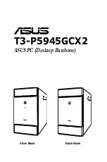
background image

T3-P5945GCX2

ASUS PC (Desktop Barebone) 

Silver Bezel 


Black Bezel

Summary of Contents for T3-P5945GCX2

Page 1: ...T3 P5945GCX2 ASUS PC Desktop Barebone Silver Bezel Black Bezel ...

Page 2: ...TICULAR PURPOSE IN NO EVENT SHALL ASUS ITS DIRECTORS OFFICERS EMPLOYEES OR AGENTS BE LIABLE FOR ANY INDIRECT SPECIAL INCIDENTAL OR CONSEQUENTIAL DAMAGES INCLUDING DAMAGES FOR LOSS OF PROFITS LOSS OF BUSINESS LOSS OF USE OR DATA INTERRUPTION OF BUSINESS AND THE LIKE EVEN IF ASUS HAS BEEN ADVISED OF THE POSSIBILITY OF SUCH DAMAGES ARISING FROM ANY DEFECT OR ERROR IN THIS MANUAL OR PRODUCT SPECIFICAT...

Page 3: ...ply unit 2 4 2 5 CPU installation 2 5 2 5 1 Installing the CPU 2 5 2 5 2 Reinstalling the CPU fan and heatsink assembly 2 7 2 6 Installing a DIMM 2 8 2 6 1 Memory configurations 2 8 2 6 2 DIMM installation 2 11 2 7 Installing an expansion card 2 12 2 7 1 Expansion slots 2 12 2 7 2 Expansion card installation 2 13 2 8 Installing an optical drive 2 14 2 9 Installing a Serial ATA disk drive 2 15 2 10...

Page 4: ...utility 5 3 5 1 2 AFUDOS utility 5 4 5 1 3 ASUS CrashFree BIOS 2 utility 5 6 5 1 4 ASUS Update utility 5 8 5 2 BIOS setup program 5 11 5 2 1 BIOS menu screen 5 12 5 2 2 Menu bar 5 12 5 2 3 Navigation keys 5 12 5 2 4 Menu items 5 13 5 2 5 Sub menu items 5 13 5 2 6 Configuration fields 5 13 5 2 7 Pop up window 5 13 5 2 8 Scroll bar 5 13 5 2 9 General help 5 13 5 3 Main menu 5 14 5 3 1 System Time 5 ...

Page 5: ...5 PCI PnP 5 22 5 5 Power menu 5 23 5 5 1 Suspend Mode 5 23 5 5 2 ACPI 2 0 Support 5 23 5 5 3 ACPI APIC Support 5 23 5 5 4 APM Configuration 5 24 5 5 5 Hardware Monitor 5 25 5 6 Boot menu 5 26 5 6 1 Boot Device Priority 5 26 5 6 2 Boot Settings Configuration 5 27 5 6 3 Security 5 28 5 7 Exit menu 5 30 Appendix Power supply specifications A 2 ...

Page 6: ...ause harmful interference to radio or television reception which can be determined by turning the equipment off and on the user is encouraged to try to correct the interference by one or more of the following measures Reorient or relocate the receiving antenna Increase the separation between the equipment and receiver Connect the equipment to an outlet on a circuit different from that to which the...

Page 7: ...e contact your dealer immediately To avoid short circuits keep paper clips screws and staples away from connectors slots sockets and circuitry Avoid dust humidity and temperature extremes Do not place the product in any area where it may become wet Place the product on a stable surface If you encounter technical problems with the product contact a qualified service technician or your retailer Lith...

Page 8: ...nel and internal components 2 Chapter 2 Basic installation This chapter provides step by step instructions on how to install components in the system 3 Chapter 3 Starting up This chapter helps you power up the system and install drivers and utilities from the support CD 4 Chapter 4 Motherboard information This chapter gives information about the motherboard that comes with the system This chapter ...

Page 9: ...n to aid in completing a task Where to find more information Refer to the following sources for additional information and for product and software updates 1 ASUS Websites The ASUS websites worldwide provide updated information on ASUS hardware and software products Refer to the ASUS contact information 2 Optional Documentation Your product package may include optional documentation such as warran...

Page 10: ... your retailer immediately Item description 1 ASUS T3 P5945GCX2 barebone system with ASUS motherboard 250 W PFC power supply unit Front I O card 6 in 1 storage card reader 2 Cables AC power cord ATA cable Serial ATA cable Serial ATA power cable 3 Support CD and Recovery Pro CD 4 Installation Manual 5 Optional items Telephone Adapter card ...

Page 11: ...lack Bezel Chapter 1 System introduction This chapter gives a general description of ASUS T3 P5945GCX2 The chapter lists the system features including introduction on the front and rear panel and internal components ...

Page 12: ...ank you for choosing ASUS T3 P5945GCX2 ASUS T3 P5945GCX2 is an all in one barebone system with a versatile home entertainment feature The system comes in a stylish mini tower casing and powered by the ASUS motherboard that supports the Intel Pentium 4 processor in the 775 land package with 533 800 1066 1333 MHz FSB and up to 4GB system memory If you are using a CPU with FSB less than 1333 MHz load...

Page 13: ... 0 These Universal Serial Bus 2 0 USB 2 0 ports are available for connecting USB 2 0 devices such as a mouse printer scanner camera PDA and others 9 Secure Digital MultimediaCard slot This slot is for a Secure Digital MultimediaCard storage card 10 Eject button Press this button to eject the optical drive tray 11 Microphone port This Mic pink port connects a microphone 12 Headphone port This port ...

Page 14: ...s Microphone pink port connects a microphone In 4 6 channel mode the function of this port becomes Low Frequency Enhanced Output Center 18 VGA port This port connects a VGA monitor 19 PS 2 mouse port This green 6 pin connector is for a PS 2 mouse 20 COM port This port connects a mouse modem or other devices that conforms with serial specification 21 PS 2 keyboard port This purple 6 pin connector i...

Page 15: ...hone or a speaker In 4 6 channel mode the function of this port becomes Front Speaker Out 28 Coaxial S PDIF Out port This port connects an external audio output device via a coaxial S PIF cable 29 Voltage selector This switch allows you to adjust the system input voltage according to the voltage supply in your area 30 Power connector This connector is for a power cable and plug 31 Power switch Thi...

Page 16: ...nsion card slot 8 Power supply unit 1 5 Internal components The illustration below is the internal view of the system when you remove the top cover and the power supply unit The installed components are labeled for your reference Proceed to Chapter 2 for instructions on installing additional system components 1 2 3 4 5 6 7 8 The illustration shows an open chassis lifted at a 90o angle ...

Page 17: ...Silver Bezel Black Bezel Chapter 2 This chapter provides step by step instructions on how to install components in the system Basic installation ...

Page 18: ...te that the system is ON in sleep mode or in soft off mode and not powered OFF Unplug the power cable from the power outlet and ensure that the standby power LED is OFF before installing any system component Use a grounded wrist strap or touch a safely grounded object or a metal object such as the power supply case before handling components to avoid damaging them due to static electricity Hold co...

Page 19: ...sis 4 Lift the cover then set aside 2 Use a Phillips screw driver to remove the cover screws Keep the screws for later use 2 3 Removing the cover To remove the cover 1 On the rear panel locate the three screws that secure the cover to the chassis 1 1 1 REAR S P K LINE IN FRONT MIC IN SIDE S P K C T R BASS 4 3 3 2 2 2 ...

Page 20: ...PU and other system components To turn over the PSU When removing the PSU ensure to hold or support it firmly The unit may accidentally drop and damage other system components 1 Lay the system chassis on its side on a flat and stable surface 2 Locate and remove the two screws that secures the PSU to the chassis 3 Lift the PSU in the direction of the arrow to a 90º angle ...

Page 21: ...transit related Keep the cap after installing the motherboard ASUS will process Return Merchandise Authorization RMA requests only if the motherboard comes with the cap on the LGA775 socket The product warranty does not cover damage to the socket contacts resulting from incorrect CPU installation removal or misplacement loss incorrect removal of the PnP cap 2 5 1 Installing the CPU Before installi...

Page 22: ... lever in the direction of the arrow to a 135º angle Load plate PnP cap 4A 4B 3 5 Position the CPU over the socket making sure that the gold triangle is on the bottom left corner of the socket then fit the socket alignment key into the CPU notch Gold triangle mark Alignment key CPU notch 6 Close the load plate A then push the load lever B until it snaps into the retention tab A B ...

Page 23: ...to install If you purchased a separate CPU heatsink and fan assembly ensure that the Thermal Interface Material is properly applied to the CPU heatsink or CPU before you install the heatsink and fan assembly To install the CPU heatsink and fan 1 Place the heatsink on top of the installed CPU making sure that the four fasteners match the holes on the motherboard 2 Push down two fasteners at a time ...

Page 24: ...1 and DIMM_B1 Always install DIMMs with the same CAS latency For optimum compatibility we recommend that you obtain memory modules from the same vendor Due to chipset resource allocation the system may detect less than 2 GB system memory when you installed two 1 GB DDR2 memory This motherboard does not support memory modules made up of 128 Mb chips or double sided x16 memory modules 2 6 1 Memory c...

Page 25: ...64M8CFEG N A DS VS1GB667D2 V 256MB ELPIDA E2508AB 6E E ELPIDA SS EBE25UC8ABFA 6E E V V 512MB ELPIDA E5108AE 6E E ELPIDA SS EBE51UD8AEFA 6E E V V 512MB A DATA AD29608A8A 3EG A DATA SS M2OAD5G3H3166I1C52 V V 1024MB A DATA AD29608A8A 3EG A DATA DS M2OAD5G3I4176I1C52 V V 2048MB A DATA NT5TU128M8BJ 3C N A DS M2ONY5H3J4170I1C5Z 512MB crucial Heat Sink Package N A SS BL6464AA663 8FD V V 1024MB crucial He...

Page 26: ... page Visit the ASUS website www asus com for the latest DDR2 Qualified Vendors List Side s SS Single sided DS Double sided DIMM support A Supports one module inserted into any slot as Single channel memory configuration B Supports one pair of modules inserted into either the yellow slots as one pair of Dual channel memory configuration ...

Page 27: ...ing clips outward 3 Align a DIMM on the socket such that the notch on the DIMM matches the break on the socket 4 Firmly insert the DIMM into the socket until the retaining clips snap back in place and the DIMM is properly seated A DDR2 DIMM is keyed with a notch so that it fits in only one direction DO NOT force a DIMM into a socket to avoid damaging the DIMM ...

Page 28: ...expansion cards Failure to do so may cause you physical injury and damage the motherboard PCI Express x16 slot This motherboard supports PCI Express x16 graphic cards that comply with PCI Express specifications The figure shows a graphics card installed on the PCI Express x16 slot The chassis supports PCI Express x 16 cards with 192 mm x 19 mm or smaller dimensions only PCI slot The PCI slot suppo...

Page 29: ...ss firmly 5 Secure the card with one screw 6 Replace the metal braket lock then secure it with one screw Standard interrupt assignments IRQ Standard Function 0 System Timer 1 Keyboard Controller 2 Programmable Interrupt 4 Communications Port COM1 6 Floppy Disk Controller 7 Printer Port LPT1 8 System CMOS Real Time Clock 9 ACPI Mode when used 10 IRQ Holder for PCI Steering 11 IRQ Holder for PCI Ste...

Page 30: ...ard USB controller 4 shared Onboard USB 2 0 controller shared Onboard IDE port shared Onboard AC 97 Audio shared Onboard LAN shared Onboard 1394 shared IRQ assignments for this motherboard 2 8 Installing an optical drive The barebone system comes with a 5 25 inch drive bays for an optical drive To install an optical drive 1 Place the chassis upright 2 Insert the optical drive to the upper 5 25 in ...

Page 31: ... of the power supply unit 2 Connect the SATA signal cable and the power plugs to the connectors at the back of the drive 3 Locate the HDD tray 4 Insert a hard disk drive with the HDD PCB facing the top of the chassis to the tray then secure it with four screws 5 Connect the SATA signal cable to the SATA connector on the motherboard and tighten all the cables with the plastic coils 1 2 4 4 4 4 4 ...

Page 32: ...supply in your area If the voltage supply in your area is 100 127 V set the switch to 115 V If the voltage supply in your area is 200 240 V set the switch to 230 V Setting the switch to 115 V in a 230 V environment will seriously damage the system REAR S P K LINE IN FRONT MIC IN SIDE S P K C T R BASS 1 If necessary connect the 4 pin 12V power plug to the ATX12V connector on the motherboard 2 If ne...

Page 33: ...t edge of the cover at least two inches from the front panel cover Fit the cover tabs with the chassis rail and the front panel tabs 3 Lower the rear edge of the cover as shown 4 Push the cover slightly toward the front panel until it fits in place 5 Secure the cover with the three screws you removed earlier 2 3 4 5 ...

Page 34: ...2 18 Chapter 2 Basic installation ...

Page 35: ...Silver Bezel Black Bezel Chapter 3 Starting up This chapter helps you power up the system and install drivers and utilities from the support CD ...

Page 36: ... Powering up The system power button is located on the front panel Press the system power button to enter the OS Press to enter the system OS Because motherboard settings and hardware options vary use the setup procedures presented in this chapter for general reference only Refer to your OS documentation for more information In Windows OS pressing the button shuts down restarts or puts the system ...

Page 37: ...ASSETUP EXE from the BIN folder Double click the ASSETUP EXE to run the CD Click an item to install Click an icon to display other information 3 3 Support CD information The support CD that came with the system contains useful software and several utility drivers that enhance the system features Screen display and driver options may not be the same for other operating system versions The contents ...

Page 38: ...rs Installation Wizard Allows you to easily install all necessary drivers for your system Intel R Chipset Inf Update Program Installs the Intel Chipset Inf Update Program Intel R Graphics Accelerator Driver Installs the Intel Graphics Accelerator driver SoundMAX ADI Audio Driver Installs the SoundMAX ADI audio driver Realtek RTL8111C 10 100 1000M LAN Driver Installs Realtek RTL8111C 10 100 1000M L...

Page 39: ...S Update Installs the ASUS Update that allows you to update the motherboard BIOS and drivers This utility requires an Internet connection either through a network or an Internet Service Provider ISP See page 5 8 for details Adobe Acrobat Reader V7 0 The Acrobat Acrobat Reader software is for viewing files saved in Portable Document Format PDF Microsoft DirectX 9 0c Installs the Microsoft DirectX 9...

Page 40: ... up 3 3 4 ASUS contact information The Contact tab displays the ASUS contact information Anti Virus Utility Installs the anti virus utility ASUS Screensaver Bring life to your idle screen by installing the ASUS Screensaver ...

Page 41: ...Bezel Black Bezel Chapter 4 Motherboard info This chapter gives information about the motherboard that comes with the system This chapter includes the motherboard layout jumper settings and connector locations ...

Page 42: ... Info 4 1 Introduction The motherboard comes already installed in ASUS T3 P5945GCX2 system This chapter provides technical information about the motherboard for future upgrades or system reconfiguration 4 2 Motherboard layout ...

Page 43: ...e RTC RAM 1 Turn OFF the computer and unplug the power cord 2 Remove the onboard battery 3 Move the jumper cap from pins 1 2 default to pins 2 3 Keep the cap on pins 2 3 for about 5 10 seconds then move the cap back to pins 1 2 4 Re install the battery 5 Plug the power cord and turn ON the computer 6 Hold down the Del key during the boot process and enter BIOS setup to re enter data Except when cl...

Page 44: ...VSB lead for each USB port Otherwise the system would not power up The total current consumed must NOT exceed the power supply capability 5VSB whether under normal condition or in sleep mode 3 Keyboard power 3 pin KBPWR This jumper allows you to enable or disable the keyboard wake up feature Set this jumper to pins 2 3 5VSB to wake up the computer when you press a key on the keyboard the default i...

Page 45: ...ctors on the motherboard 1 CPU fan connector 4 pin CPU_FAN The fan connector supports the proprietary CPU fan Connect the fan cable to the fan connector on the motherboard making sure that the black wire of each cable matches the ground pin of the connector Do not forget to connect the fan cable to the fan connector Insufficient air flow within the system may damage the motherboard components Thes...

Page 46: ...XPWR 3 Volts 3 Volts Ground 5 Volts 5 Volts Ground Ground Power OK 5V Standby 12 Volts 5 Volts 5 Volts 3 Volts 12 Volts Ground Ground Ground PSON Ground 5 Volts 12 Volts 3 Volts 5 Volts Ground ATX12V GND 12V DC GND 12V DC R 3 IDE connector 40 1 pin PRI_IDE This connector is for an IDE 100 66 signal cable a blue connector for the primary IDE connector on the motherboard Pin 20 on the IDE connector ...

Page 47: ...connections Connect the right angle side of SATA signal cable to SATA device Or you may connect the right angle side of SATA cable to the onboard SATA port to avoid mechanical conflict with huge graphics cards right angle side Serial ATA hard disk drive connection Connector Color Setting Use SATA1 2 Red Master Boot disk SATA3 Red Slave Data Disk GND RSATA_TXP3 RSATA_TXN3 GND RSATA_RXP3 RSATA_RXN3 ...

Page 48: ...4 Chapter 4 Motherboard Info 5 Optical drive audio connector 4 pin CD These connectors allow you to receive stereo audio input from sound sources such as a CD ROM TV tuner or MPEG card ...

Page 49: ... Silver Bezel Black Bezel Chapter 5 BIOS setup This chapter tells how to change system settings through the BIOS Setup menus and describes the BIOS parameters ...

Page 50: ...a bootable floppy disk in DOS mode 3 ASUS CrashFree BIOS 2 Updates the BIOS using a bootable floppy disk or the motherboard support CD when the BIOS file fails or gets corrupted 4 ASUS Update Updates the BIOS in Windows environment Refer to the corresponding sections for details on these utilities Save a copy of the original motherboard BIOS file to a bootable floppy disk in case you need to resto...

Page 51: ...g POST to display the following EZFlash starting BIOS update Checking for floppy 4 Insert the floppy disk that contains the BIOS file to the floppy disk drive When the correct BIOS file is found EZ Flash performs the BIOS update process and automatically reboots the system when done EZFlash starting BIOS update Checking for floppy Floppy found Reading file P5L13LSE rom Completed Start erasing Star...

Page 52: ...pt type afudos o filename where the filename is any user assigned filename not more than eight alphanumeric characters for the main filename and three alphanumeric characters for the extension name Make sure that the floppy disk is not write protected and has at least 600 KB free space to save the file The succeeding BIOS screens are for reference only The actual BIOS screen displays may not be ex...

Page 53: ...therboard Save the BIOS file to a bootable floppy disk 4 The utility reads the file and starts updating the BIOS Do not shut down or reset the system while updating the BIOS to prevent system boot failure Write the BIOS filename on a piece of paper You need to type the exact BIOS filename at the DOS prompt A afudos iP5L13LSE ROM AMI Firmware Update Utility Version 1 19 ASUS V2 07 03 11 24BB Copyri...

Page 54: ...1 3 ASUS CrashFree BIOS 2 utility The ASUS CrashFree BIOS 2 is an auto recovery tool that allows you to restore the BIOS file when it fails or gets corrupted during the updating process You can update a corrupted BIOS file using the motherboard support CD or the floppy disk that contains the updated BIOS file Recovering the BIOS from a floppy disk To recover the BIOS from a floppy disk 1 Turn on t...

Page 55: ...tomatically checks the optical drive for the original or updated BIOS file The utility then updates the corrupted BIOS file Bad BIOS checksum Starting BIOS recovery Checking for floppy Bad BIOS checksum Starting BIOS recovery Checking for floppy 4 Restart the system after the utility completes the updating process Bad BIOS checksum Starting BIOS recovery Checking for floppy Floppy found Reading fi...

Page 56: ... the Utilities screen menu 3 The ASUS Update utility is copied to your system 5 1 4 ASUS Update utility The ASUS Update is a utility that allows you to manage save and update the motherboard BIOS in Windows environment The ASUS Update utility allows you to Save the current BIOS file Download the latest BIOS file from the Internet Update the BIOS from an updated BIOS file Update the BIOS directly f...

Page 57: ...xt Updating the BIOS through the Internet To update the BIOS through the Internet 1 Launch the ASUS Update utility from the Windows desktop by clicking Start Programs ASUS ASUSUpdate ASUSUpdate The ASUS Update main window appears 2 Select Update BIOS from the Internet option from the drop down menu then click Next ...

Page 58: ...date BIOS from a file option from the drop down menu then click Next 4 From the FTP site select the BIOS version that you wish to download Click Next 5 Follow the screen instructions to complete the update process The ASUS Update utility is capable of updating itself through the Internet Always update the utility to avail all its features 3 Locate the BIOS file from the Open window then click Open...

Page 59: ...ish to enter Setup after POST reboot the system by doing any of the following procedures Restart using the OS standard shut down procedure Press Ctrl Alt Del simultaneously Press the reset button on the system chassis Press the power button to turn the system off then back on Using the power button reset button or the Ctrl Alt Del keys to force reset from a running operating system can cause damag...

Page 60: ...until the desired item is highlighted 5 2 3 Navigation keys At the bottom right corner of a menu screen are the navigation keys for that particular menu Use the navigation keys to select items in the menu and change the settings Use ENTER TAB or SHIFT TAB to select a field Use or to configure the System time Navigation keys General help Menu bar Sub menu items Configuration fields Menu items Some ...

Page 61: ...er to display a list of options Refer to 5 2 7 Pop up window 5 2 7 Pop up window Select a menu item then press Enter to display a pop up window with the configuration options for that item 5 2 8 Scroll bar A scroll bar appears on the right side of a menu screen when there are items that do not fit on the screen Press the Up Down arrow keys or Page Up Page Down keys to display the other items on th...

Page 62: ...ws you to set the system date Refer to section 5 2 1 BIOS menu screen for information on the menu screen items and how to navigate through them Use ENTER TAB or SHIFT TAB to select a field Use or to configure the System time System Time 16 37 21 System Date Mon 10 20 2004 Primary IDE Master Not Detected Primary IDE Slave Not Detected Third IDE Master Not Detected Third IDE Slave Not Detected Fouth...

Page 63: ...movable Media Device if your device is either a ZIP LS 120 or MO drive Configuration options Not Installed Auto CDROM ARMD LBA Large Mode Auto Enables or disables the LBA mode Setting to Auto enables the LBA mode if the device supports this mode and if the device was not previously formatted with LBA mode disabled Configuration options Disabled Auto Block Multi sector Transfer Auto Enables or disa...

Page 64: ... ATA ATAPI device s PIO Mode Auto Selects the PIO mode Configuration options Auto 0 1 2 3 4 DMA Mode Auto Selects the DMA mode Configuration options Auto SMART Monitoring Auto Sets the Smart Monitoring Analysis and Reporting Technology Configuration options Auto Disabled Enabled 32Bit Data Transfer Disabled Enables or disables 32 bit data transfer Configuration options Disabled Enabled IDE Detect ...

Page 65: ... system memory AMIBIOS Version 0104 Build Date 09 19 07 Processor Type Intel R Core TM CPU 6300 1 86GHz Speed 1866 MHz Count 2 System Memory Total 512 MB Available 504 MB 5 4 Advanced menu The Advanced menu items allow you to change the settings for the CPU and other system devices Take caution when changing the settings of the Advanced menu items Incorrect field values can cause the system to mal...

Page 66: ...st controllers Configuration options Enabled Disabled Legacy USB Support Auto Allows you to enable or disable support for USB devices on legacy operating systems OS Setting to Auto allows the system to detect the presence of USB devices at startup If detected the USB controller legacy mode is enabled If no USB device is detected the legacy USB support is disabled Configuration options Disabled Ena...

Page 67: ... Control Auto Virtualization Technology Enabled Enable or Disable Microcode Update Execute Disable Function Disabled Allows you to enable or disable the no execution on page protection technology When enabled the system forces the XD features flag to always return to zero Configuration options Disabled Enabled Enhanced C1 Control Auto Allows you to enable or disable the Enhanced C1 control functio...

Page 68: ...ty PCI Express Int VGA Allows selection of the graphics controller to use as primary boot device Configuration options Internal VGA PCI Express Int VGA PCI Express PCI PCI PCI Express PCI Int VGA Internal Graphics Mode Select Enabled 8MB Sets the internal graphics mode Configuration options Disabled Enabled 1MB Enabled 8MB Enable or disable Configure DRAM Timing by SPD Intel SpeedStep tm Technolog...

Page 69: ... Controller Enabled Enables or disables the onboard IEEE 1394a controller Configuration options Enabled Disabled Onboard PCIEX GbE LAN Enabled Allows you to enable or disable the onboard LAN controller Configuration options Enabled Disabled LAN Boot ROM Disabled Allows you to enable or disable onboard PCIEX GbE LAN Boot ROM Configuration options Disabled Enabled Serial Port1 Address 3F8 IRQ4 Allow...

Page 70: ... and Play O S No When set to No BIOS configures all the devices in the system When set to Yes and if you install a Plug and Play operating system the operating system configures the Plug and Play devices not required for boot Configuration options No Yes PCI Latency Timer 64 Allows you to select the value in units of PCI clocks for the PCI device latency timer register Configuration options 32 64 ...

Page 71: ...cifications Configuration options No Yes 5 5 3 ACPI APIC Support Enabled Allows you to enable or disable the Advanced Configuration and Power Interface ACPI support in the Advanced Programmable Interrupt Controller APIC When set to Enabled the ACPI APIC table pointer is included in the RSDT pointer list Configuration options Disabled Enabled Suspend Mode Auto ACPI 2 0 Support No ACPI APIC Support ...

Page 72: ...RTC Alarm Date RTC Alarm Hour RTC Alarm Minute and RTC Alarm Second appear with set values Configuration options Disabled Enabled Power On By External Modems Disabled This allows either settings of Enabled or Disabled for powering up the computer when the external modem receives a call while the computer is in Soft off mode Configuration options Disabled Enabled Power On By PCI Devices Disabled Wh...

Page 73: ...etects and displays the motherboard and CPU temperatures Select Disabled if you do not wish to display the detected temperatures CPU Fan Speed RPM xxxxRPM N A or Ignored The onboard hardware monitor automatically detects and displays the CPU fan speed in rotations per minute RPM If the fan is not connected to the motherboard the field shows N A Power On By PS 2 Keyboard Disabled Allows you to use ...

Page 74: ...rd voltage regulators 5 6 Boot menu The Boot menu items allow you to change the system boot options Select an item then press Enter to display the sub menu Boot Settings Boot Priority Boot Settings Configuration Security 5 6 1 Boot Device Priority 1st xxth Boot Device These items specify the boot device priority sequence from the available devices The number of device items that appears on the scr...

Page 75: ...crease the time needed to boot the system When set to Disabled BIOS performs all the POST items Configuration options Disabled Enabled Full Screen Logo Enabled This allows you to enable or disable the full screen logo display feature Configuration options Disabled Enabled Bootup Num Lock On Allows you to select the power on state for the NumLock Configuration options Off On Hit DEL Message Display...

Page 76: ...et a password this item shows Installed To set a Supervisor Password 1 Select the Change Supervisor Password item and press Enter 2 From the password box type a password composed of at least six letters and or numbers then press Enter 3 Confirm the password when prompted The message Password Installed appears after you successfully set your password To change the supervisor password follow the sam...

Page 77: ...ssword The User Password item on top of the screen shows the default Not Installed After you set a password this item shows Installed To set a User Password 1 Select the Change User Password item and press Enter 2 On the password box that appears type a password composed of at least six letters and or numbers then press Enter 3 Confirm the password when prompted The message Password Installed appe...

Page 78: ...ption a confirmation appears Select OK to discard any changes and load the previously saved values Load Setup Defaults This option allows you to load the default values for each of the parameters on the Setup menus When you select this option or if you press F5 a confirmation window appears Select OK to load default values Select Exit Save Changes or make other changes before saving the values to ...

Page 79: ...Silver Bezel Black Bezel Appendix Appendix The Appendix includes the power supply unit specification for this system ...

Page 80: ...stics Output voltage Load range Regulation Ripple and noise Min Max Vpp Vpp noise 5V 0 3A 18A 5 5 50mV 70mV 3 3V 0 3A 16A 5 5 50mV 70mV 12V1 1A 10A 12A 5 5 150mV 150mV 12V2 1A 14A 18A 5 5 150mV 150mV 12V 0A 0 3A 10 10 200mV 200mV 5VSB 0 1A 2 5A 5 5 50mV 70mV ...

Reviews: