background image

Server User Guide

TS700-E8-PS4 V2

TS700-E8-RS8 V2

Summary of Contents for TS700-E8-PS4 V2

Page 1: ...Server User Guide TS700 E8 PS4 V2 TS700 E8 RS8 V2 ...

Page 2: ...tion of business and the like even if ASUS has been advised of the possibility of such damages arising from any defect or error in this manual or product Specifications and information contained in this manual ae furnished for informational use only and are subject to change at any time without notice and should not be construed as a commitment by ASUS ASUS assumes no responsibility or liability f...

Page 3: ...ing the CPU 2 4 2 2 2 Installing the CPU heatsink 2 9 2 3 System memory 2 10 2 3 1 Overview 2 10 2 3 2 Memory Configurations 2 10 2 3 3 Installing a DIMM on a single clip DIMM socket 2 12 2 3 4 Removing a DIMM from a single clip DIMM socket 2 12 2 4 Front panel assembly 2 13 2 4 1 Removing the front panel assembly 2 13 2 4 2 Reinstalling the front panel assembly 2 13 2 5 SATA SAS hard disk drives ...

Page 4: ... Preparing the system for rack mounting 3 2 3 2 Attaching the inner rail to the server 3 2 3 3 Attaching the rails to the rack 3 3 3 4 Mounting the server to the rack 3 4 Chapter 4 Motherboard Info 4 1 Motherboard layout 4 2 4 2 Onboard LEDs 4 4 4 3 Onboard buttons switches and jumpers 4 12 4 3 1 Onboard buttons and switches 4 12 4 3 2 Jumpers 4 14 4 4 Internal connectors 4 18 Chapter 5 BIOS setup...

Page 5: ...ubsystem Settings 5 22 5 5 9 Network Stack Configuration 5 23 5 5 10 CSM Configuration 5 24 5 5 11 Trusted Computing 5 25 5 5 12 USB Configuration 5 26 5 5 13 iSCSI Configuration 5 27 5 6 IntelRCSetup menu 5 28 5 6 1 Processor Configuration 5 29 5 6 2 Advanced Power Management Configuration 5 31 5 6 3 Common RefCode Configuration 5 32 5 6 4 QPI Configuration 5 33 5 6 5 Memory Configuration 5 34 5 ...

Page 6: ...6 6 2 5 Checking the drives for data consistency 6 18 6 2 6 Deleting a RAID configuration 6 21 6 2 7 Selecting the boot drive from a RAID set 6 22 6 2 8 Enabling WriteCache 6 23 6 3 Intel Rapid Storage Technology enterprise SATA SSATA Option ROM Utility 6 24 6 3 1 Creating a RAID set 6 25 6 3 2 Deleting a RAID set 6 27 6 3 3 Resetting disks to Non RAID 6 28 6 3 4 Exiting the Intel Rapid Storage Te...

Page 7: ...driver 7 3 7 2 Software drivers and utilities installation 7 13 7 3 Running the Support DVD 7 13 7 4 Installing the drivers and utilities 7 16 7 4 1 Using the ASUS InstAll application 7 16 7 4 2 Installing a driver or utility 7 18 7 5 Running the utilities 7 20 7 5 1 USB Charger 7 20 Appendix Z10PE D16 WS block diagram A 2 ASUS contact information A 3 ...

Page 8: ...the user is encouraged to try to correct the interference by one or more of the following measures Reorient or relocate the receiving antenna Increase the separation between the equipment and receiver Connect the equipment to an outlet on a circuit different from that to which the receiver is connected Consult the dealer or an experienced radio TV technician for help Canadian Department of Communi...

Page 9: ...server carefully read all the manuals included with the server package Before using the server ensure all cables are correctly connected and the power cables are not damaged If any damage is detected contact your dealer as soon as possible To avoid short circuits keep paper clips screws and staples away from connectors slots sockets and circuitry Avoid dust humidity and temperature extremes Place ...

Page 10: ...al waste Australia statement notice From 1 January 2012 updated warranties apply to all ASUS products consistent with the Australian Consumer Law For the latest product warranty details please visit http support asus com Our goods come with guarantees that cannot be excluded under the Australian Consumer Law You are entitled to a replacement or refund for a major failure and compensation for any o...

Page 11: ...ions This chapter describes how to install optional components into the barebone server 4 Chapter 4 Motherboard information This chapter gives information about the motherboard that comes with the server This chapter includes the motherboard layout jumper settings and connector locations 5 Chapter 5 BIOS information This chapter tells how to change system settings through the BIOS Setup menus and ...

Page 12: ...emphasize a word or a phrase Key Keys enclosed in the less than and greater than sign means that you must press the enclosed key Example Enter means that you must press the Enter or Return key Key1 Key2 Key3 If you must press two or more keys simultaneously the key names are linked with a plus sign Example Ctrl Alt Del Command Means that you must type the command exactly as shown then supply the r...

Page 13: ...1 Product Introduction This chapter describes the motherboard features and the new technologies it supports Chapter 1 Product Introduction ...

Page 14: ...edundant Power Supply Module TS700 E8 RS8 V2 4 x Hot swap 3 5 inch HDD Trays Front panel TS700 E8 PS4 V2 8 x Hot swap 3 5 inch HDD Trays Front panel TS700 E8 RS8 V2 2 x Hot swap 2 5 inch SSD Trays Rear panel TS700 E8 RS8 V2 only 1 x SAS SATA backplane TS700 E8 PS4 V2 2 x SAS SATA backplanes TS700 E8 RS8 V2 1 x Front I O Board 3 x System Fans Front 2 x 80mm x 38mm Rear 1 x 120mm x 38mm Accessories ...

Page 15: ... you must take note of the product s serial number containing 12 characters such as xxS0xxxxxxxx shown as the figure below With the correct serial number of the product ASUS Technical Support team members can then offer a quicker and satisfying solution to your problems xxS0xxxxxxxx TS700 E8 PS4 V2 xxS0xxxxxxxx TS700 E8 RS8 V2 ...

Page 16: ...d 4GB RDIMM 64GB 32GB LRDIMM Refer to www asus com for the latest memory AVL update Expansion Slots follow SSI Location Total PCI PCI E Slots 6 Slot Type 4 x PCI E x16 Gen3 x16 link Full height FL 1 x PCI E x16 Gen3 x8 link Full height FL 1 x PCI E x16 Gen3 x8 link Full height HL Storage SATAController Intel C612 10 x SATA 6 Gbps ports or 9 x SATA 6 Gbps ports 1 x discrete M 2 socket Intel RSTe fo...

Page 17: ...s Server 2012 Windows Server 2008 R2 RedHat Enterprise Linux SuSE Liunx Enterprise Server CentOS Unbuntu VMWare Citrix XenServer Support versions are subject to change without notice Refer to www asus com for updates Management Solution Software ASWM Enterprise Out of Band Remote Management ASMB8 iKVM for KVM over Internet Dimensions HH x WW x DD 455 mm x 217 50 mm x 545 00 mm Net Weight Kg CPU DR...

Page 18: ...IKE card before using eight hot swap 3 5 inch HDDs LAN port 3 LAN port 1 Q Code Logger Management USB BIOS Flashback SPDIF OUT USB3 0 USB3 0 side MIC IN LINE OUT LINE IN KY rear c sub 1 2 Optical drive optional 2 x Empty 5 25 inch bays Power button Reset button Message LED HDD access LED Power LED 2 x USB 2 0 ports 4 bay HDD module First set LAN1 LED LAN2 LED Location LED Reserved Security lock 2 ...

Page 19: ...nagement USB BIOS Flashback SPDIF OUT USB3 0 USB3 0 side MIC IN LINE OUT LINE IN KY rear c sub Power connector Expansion slots 120mm x 38mm system fan PS 2 keyboard mouse combo port 4 x USB 3 0 ports 2 x USB 2 0 ports Q Code Logger button with LED BIOS Flashback button with LED Management LAN port VGA port SPDIF Out port 2 x USB 2 0 ports Audio I O ports LAN RJ 45 port 2 LAN RJ 45 port 1 ...

Page 20: ...ower connectors Expansion slots 120mm x 38mm system fan PS 2 keyboard mouse combo port 4 x USB 3 0 ports 2 x USB 2 0 ports Q Code Logger button with LED BIOS Flashback button with LED Management LAN port VGA port SPDIF Out port 2 x USB 2 0 ports Audio I O ports LAN RJ 45 port 2 LAN RJ 45 port 1 2 x 2 5 inch SSD bays This port is for ASUS ASMB8 iKVM controller and for technicians only ...

Page 21: ...drive bays 8 4 bay HDD module First set with backplane TS700 E8 PS4 V2 only supports this set 9 4 bay HDD module Second set with backplane TS700 E8 RS8 V2 only 10 2 x 80mm x 38mm system fans hidden beside the backplane 11 2 x 2 5 inch SSD bays TS700 E8 RS8 V2 only The barebone server does not include a floppy disk drive Connect a USB floppy disk drive to any of the USB ports on the front or rear p...

Page 22: ... ASWM to check the abnormal status HDD Status LED Green Bridge board connected to backplane Installed HDD is in good condition Red HDD failure Green Red Blinking HDD rebuilding using the RAID card LAN LEDs OFF No LAN connection Blinking LAN is transmitting or receiving data ON LAN connection is present L 1 2 Message LED HDD Status LED Power LED LAN1 LED LAN2 LED HDD access LED Location LED Reserve...

Page 23: ...ion Status Description OFF No link OFF 10 Mbps connection ORANGE Linked ORANGE 100 Mbps connection BLINKING Data activity GREEN 1 Gbps connection Q Code Logger Management USB BIOS Flashback SPDIF OUT USB3 0 USB3 0 side MIC IN LINE OUT LINE IN KY rear c sub SPEED LED ACT LINK LED SPEED LED ACT LINK LED ...

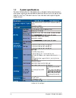
Page 24: ...Chapter 1 Product Introduction 1 12 ...

Page 25: ...This chapter lists the hardware setup procedures that you have to perform when installing or removing system components Chapter 2 Hardware Information 2 Hardware Information ...

Page 26: ...e side cover Keep your fingers from components inside the chassis that can cause injury such as the CPU fan rear fan and other sharp edged parts To remove the side cover 1 Remove the two screws that secure the side cover 2 Slide the side cover for about half an inch toward the rear until it is disengaged from the chassis 3 Carefully lift the side cover and set it aside 2 3 1 1 ...

Page 27: ...r To reinstall the side cover 1 Match and insert the lower sliding edge of the side cover to the corresponding chassis edge 2 Slide the side cover toward the front panel until it snaps in place 3 Drive in the two screws you removed earlier to secure the side cover 2 1 3 3 1 ...

Page 28: ...ontacts motherboard components Keep the cap after installing the motherboard ASUS will process Return Merchandise Authorization RMA requests only if the motherboard comes with the cap on the LGA 2011 3 socket The product warranty does not cover damage to the socket contacts resulting from incorrect CPU installation removal or misplacement loss incorrect removal of the PnP cap 2 2 1 Installing the ...

Page 29: ...until it is released from the retention tab B then gently lift the load lever C To prevent damage to the socket pins do not remove the PnP cap unless you are installing a CPU 3 Press the right load lever with your thumb D move it to the left E until it is released from then gently lift the load lever F Load lever ...

Page 30: ...the load lever into the retention tab The CPU fits in only one correct orientation DO NOT force the CPU into the socket to prevent bending the CPU pins on the socket 6 Get the CPU 7 Align and position the CPU over the socket ensuring that the triangle mark on the CPU matches the triangle mark on the socket box 5 Hold the edge then gently lift the load plate H 8 Install the CPU into the slot Edge o...

Page 31: ...t load lever under the retention tab K The PnP cap pops out of the load plate when the right load lever is inserted into the retention tab Keep the PnP cap ASUS will process Return Merchandise Authorization RMA requests only if the motherboard comes with the PnP cap on the LGA 2011 socket 11 Push down the left load lever L then insert it under the retention tab M PnP cap Retention tab ...

Page 32: ... skin wash it off immediately and seek professional medical help Ensure that the Thermal Interface Material is spread in an even thin layer Some heatsinks come with pre applied Thermal Interface Material If so skip this step 12 Apply some Thermal Interface Material to the exposed area of the CPU that the heatsink will be in contact with ...

Page 33: ...h the holes on the support plate and the arrow on the fan faces the rear panel of the server chassis 2 Twist each of the four screws with a Philips cross screwdriver just enough to attach the CPU heatsink and fan to the motherboard When the four screws are attached tighten them one by one to completely secure the CPU heatsink and fan A B B A Tighten the four heatsink screws in a diagonal sequence ...

Page 34: ...ry Configurations You may install 4 GB 8 GB 16 GB and 32 GB RDIMMs or 32 GB and 64 GB LR DIMMs into the DIMM sockets using the memory configurations in this section Refer to ASUS Server AVL for the updated list of compatible DIMMs When installing DIMMs always start from slot A1 CPU1 and E1 CPU2 Always install DIMMs with the same CAS latency For optimum compatibility it is recommended that you obta...

Page 35: ...ommended memory population for a single CPU configuration Dual CPU configuration DIMM CPU1 DIMM CPU2 A2 A1 B2 B1 C2 C1 D2 D1 E2 E1 F2 F1 G2 G1 H2 H1 2 DIMMs P P 4 DIMMs P P P P 8 DIMMs P P P P P P P P 12 DIMMs P P P P P P P P P P P P 16 DIMMs P P P P P P P P P P P P P P P P Single CPU configuration must be installed on CPU1 DIMM A2 A1 B2 B1 C2 C1 D2 D1 1 DIMM P 2 DIMMs P P 4 DIMMs P P P P 8 DIMMs ...

Page 36: ...IMM notch DIMM slot key 1 Press the retaining clip outward to unlock the DIMM 2 Remove the DIMM from the socket 2 3 4 Removing a DIMM from a single clip DIMM socket To install two or more DIMMs refer to the user guide bundled with the motherboard package Refer to the user guide for qualified vendor lists of the memory modules Support the DIMM lightly with your fingers when pressing the retaining c...

Page 37: ... 2 4 1 Removing the front panel assembly To remove the front panel assembly 1 Locate the three hooked tabs on the chassis side rail 2 Shift the hooked tabs and take off the front bezel 2 4 2 Reinstalling the front panel assembly To reinstall the front panel assembly 1 Hook the other side of the front panel assembly to the chassis 2 Swing the front panel assembly and snap it back into place ...

Page 38: ...ot swap SATA SAS hard disk drives allows you to access the drive trays by simply opening the front bezel An HDD module cage comes with a SATA or SAS backplane Take note of the type of HDD module cage you purchase before buying hard disks 2 5 1 Removing the HDD module cage 1 Disconnect all the cables from the SATA SAS backplane on the HDD module cage 2 Level the HDD module cage latch counterclockwi...

Page 39: ... HDD module cage latch counterclockwise 3 Insert the HDD module cage into the bay 4 When the HDD module cage is completely inserted the cage latch will be pushed back clockwise 5 Lock the cage latch properly 6 Connect the appropriate cables to the SATA SAS backplane on the HDD module cage 2 3 4 5 By default only TS700 E8 RS8 V2 supports the second set of HDD module ...

Page 40: ... SATA SAS backplane 3 Loosen the four screws on the backplane 4 Firmly hold the backplane and turn it in the direction of the arrow 5 Remove the backplane from the module 2 5 4 Installing a hot swap SATA SAS hard disk drive 1 Release a drive tray by pushing the spring lock to the right and then pulling the tray lever outward The drive tray ejects slightly after you pull out the lever ...

Page 41: ... hard disk drives Use two screws on each side to secure the hard disk drive 4 Place a SATA SAS hard disk drive on the tray and then secure it with four screws 5 Carefully insert the drive tray and push it all the way to the depth of the bay until just a small fraction of the tray edge protrudes When installed the SATA SAS connector on the drive connects to the SATA SAS interface on the backplane ...

Page 42: ...r panel for mounting SATA SAS or SSD hard disk drives To install a 2 5 inch hard disk drive 1 Release a drive tray by pushing the spring lock to the right and then pulling the tray lever outward The drive tray ejects slightly after you pull out the lever Support beam 3 Place the drive tray on a flat surface 4 Release the screws on each side of the drive tray to release the drive tray metal beam 5 ...

Page 43: ... the SATA SAS connector on the drive connects to the SATA SAS interface on the backplane 9 Repeat steps 1 to 8 to install other 2 5 inch hard disk drives 7 Carefully insert the drive tray with its case facing downwards and push it all the way to the drive bay 8 Lock the secure tab to secure the drive tray in place When the drive tray assembly is properly installed you will see the edge of the driv...

Page 44: ...beled 2 and 3 are available for additional 5 25 inch drives or 5 25 inch to 3 5 inch hard drive adapter for installing 3 5 inch zip or floppy disk drives You must remove the front panel assembly before installing a 5 25 inch drive 2 6 1 Installing a 5 25 inch drive 1 Unscrew and remove the metal cover of the bay where you want to install the 5 25 inch drive 2 Insert the drive into the bay and slid...

Page 45: ...stem components 2 7 1 Installing an expansion card 1 Before installing the expansion card read the documentation that came with it and make the necessary hardware settings for the card TS700 E8 PS4 V2 supports up to three GPU cards TS700 E8 RS8 V2 supports only one GPU card 2 Remove the side chassis cover Lay the system on its side on a flat stable surface 4 Remove the metal slot cover 3 Release t...

Page 46: ...lign the card s golden fingers with the slot and then press firmly until the card is completely seated on the slot 6 Secure the expansion card with the screws that you removed earlier in step 3 7 When installing a PCIex16 graphics card that requires external power supply connect the 6 2 pin connector of the bundled power cable to the graphics card ...

Page 47: ... card You can install an ASUS PIKE II card on the provided PCI E slot onboard To install an ASUS PIKE II card 1 Remove the default cable from the motherboard and the backplane 2 Remove the screw on the metal cover and then remove the metal cover put them aside for future use ...

Page 48: ...or 1 3 Prepare your ASUS PIKE II card 4 Insert the expansion card into the PCI E slot Ensure that the golden fingers are totally inserted into the slot 5 Connect the two mini SAS HD cables to the ASUS PIKE II card Connect only one 1 mini SAS HD cable to ASUS PIKE II connector 1 for TS700 E8 PS4 V2 ...

Page 49: ... 2 6 Connect connector 1 on the ASUS PIKE II card to connector 1 on the backplane and connector 2 on the ASUS PIKE II card to connector 2 on the backplane using two mini SAS HD cables Connect only one 1 mini SAS HD cable to backplane connector 1 for TS700 E8 PS4 V2 ...

Page 50: ...e drivers for the expansion card Standard Interrupt assignments IRQ Priority Standard function 0 1 System Timer 1 2 Keyboard Controller 2 Programmable Interrupt 3 11 Communications Port COM2 4 12 Communications Port COM1 5 13 6 14 Floppy Disk Controller 7 15 8 3 System CMOS Real Time Clock 9 4 ACPI Mode when used 10 5 IRQ Holder for PCI Steering 11 6 IRQ Holder for PCI Steering 12 7 PS 2 Compatibl...

Page 51: ...8 V2 Expansion slots PCIEX16_1 1 x PCIE x16 x8 Gen3 Link PCIEX16_2 1 x PCIE X16 x16 Gen3 Link PCIEX16_3 1 x PCIE x16 x8 Gen3 Link PCIEX16_4 1 x PCIE X16 x16 Gen3 Link PCIEX16_5 1 x PCIE x16 x16 Gen3 Link PCIEX16_6 1x PCIE x16 x16 Gen3 Link ...

Page 52: ...oard To install an M 2 expansion card 1 Remove the screw on the M 2 socket and set it aside 2 Find your M 2 expansion card 3 Align and insert the M 2 card into the M 2 slot onboard as shown 4 Secure the M 2 card with a screw that you removed earlier in step 1 The illustrations below vary with models The installation steps are the same M2 socket 4 3 ...

Page 53: ...om power supply to motherboard 2 8 pin 12V power connector from power supply to motherboard 3 System fan connector from system fan to motherboard 4 USB 3 0 connector from motherboard to front I O board 5 USB 2 0 connector from motherboard to front I O board 6 SATA connector system default from motherboard to front 3 5 inch SATA SAS backplane 7 SSATA connector system default from motherboard to opt...

Page 54: ...to the front panel LEDs to indicate HDD status See section 1 7 LED information for details Front side The front side of the SATA SAS backplane faces the front panel when installed This side includes four SATA SAS connectors for the hot swap drive trays Each SATA SAS connector is labeled HDD1 HDD2 HDD3 HDD4 so you can easily determine their counterpart connectors at the back side of the backplane R...

Page 55: ...nectors and SATA SAS interfaces for the motherboard Serial ATA connectors or the SAS card BPSMB1 PWR1 MSAS_HD1 Connectors Description MSAS_HD1 Connects to SATA SGPIO1 connector on the motherboard or connects to SATA SAS connectors on the ASUS PIKE II card BPSMB1 Connects to AUX_PANEL1 connector on the motherboard PWR1 Connects to 4 pin plug of the power supply ...

Page 56: ...ctive components This section tells how to remove the following components 1 System fans front and rear 2 Redundant power supply module 3 Chassis footpads LAN port 3 LAN port 1 Q Code Logger Management USB BIOS Flashback SPDIF OUT USB3 0 USB3 0 side MIC IN LINE OUT LINE IN KY rear c sub 1 2 1 1 2 Locate the front system fan near the 5 25 inch drive bays 3 Squeeze the front system fan latches step ...

Page 57: ...ueeze the front system fan latches step a and pull out the front system fan step b as shown in the figure below 2 Unplug the system fan cable from the REAR_FAN1 connector on the motherboard 3 Carefully remove the system fan Follow the previous instructions in reverse to reinstall the rear system fan a a b ...

Page 58: ...ocate the redundant power supply you want to remove on the rear panel of your chassis Move the handle on it upward 2 Press the latch to the left and pull the power supply module out of the system chassis 3 Insert the replacement power supply module into the chassis You will hear a sound when the power supply module is secured in place ...

Page 59: ...to remove these footpads if you wish to install the system to a rack Refer to Chapter 3 Installation options of this user guide and to the Rackmount Kit user guide for instructions To remove the footpads 1 Lay the system chassis on its side 2 Remove the footpad by rotating it counterclockwise with a Philips cross screwdriver 3 Repeat steps 1 and 2 to remove the other three footpads ...

Page 60: ...Chapter 2 Hardware Setup 2 36 ...

Page 61: ...This chapter describes how to install the optional components and devices into the barebone server 3 Installation Options Chapter 3 Installation Options ...

Page 62: ...erformance Removing the footpads Refer to section 2 9 3 Chassis footpads for instructions on removing the footpads Removing the top cover Unscrew and slide the top cover toward the rear panel and then lift it up from the chassis 3 2 Attaching the inner rail to the server 2 Slide the inner rail into the rail on top of the chassis 3 Align the screw holes on the inner rail and the chassis top and the...

Page 63: ...ail to the bottom of the chassis with screws 1U space 3 3 Attaching the rails to the rack To attach the rails to the rack 1 Select one unit of space 1U on the rack where you wish to install the server 2 Drive in two screws on the rack rails 5 Use three screws to secure the side hooks to both rails ...

Page 64: ...nto the rack secure both sides using screws 5 Find the rear 1U space that corresponds to the front 1U space where you attached the rail Drive in two screws on the outer holes to secure the rear end 6 From the rack front find the corresponding 1U space for the second rail pair 7 Repeat steps 3 6 to attach the second rail pair 3 Align the front end holes of a rack rail pair to the 1U space 4 Drive i...

Page 65: ...This chapter includes the motherboard layout and brief descriptions of the jumpers and internal connectors 4 Motherboard Info Chapter 4 Motherboard Info ...

Page 66: ...ED ERR_DIMMA1 ERR_DIMMB1 ERR_DIMMC1 ERR_DIMMD1 ERR_DIMME1 ERR_DIMMF1 ERR_DIMMG1 ERR_DIMMH1 4 4 2 Baseboard Management Controller LED BMC_LED1 4 4 3 Location LED LOCLED2 4 5 4 CATT LED CATTERR_LED1 4 5 5 CPU Warning LED ERR_CPU1 ERR_CPU2 4 6 6 M2 LED M2_LED 4 6 7 ASUS Dr Power LED PGLED3 4 7 8 Q Code LED LED1 4 8 ...

Page 67: ...supply SMBus Connector PSUSMB1 4 20 6 Serial port connectors 10 1 pin COM1 4 20 7 Serial ATA 6 0 3 0 Gb s connectors 7 pin SATA_1 6 gray Serial ATA 6 0 3 0 Gb s connectors 7 pin SSATA_1 4 gray 4 21 8 Serial General Purpose Input Output connector 6 1 pin SGPIO1 SSGPIO1 4 22 9 M 2 NGFF connector NGFF1 4 22 10 Trusted Platform Module connector 20 1 pin TPM1 4 23 11 EATX power connectors 24 pin EATXPW...

Page 68: ... indicate an error in its nearby DIMM 4 2 Onboard LEDs 2 Baseboard Management Controller LED BMC_LED1 The BMC LED works with the ASUS ASMB8 management device and indicates its initiation status When the PSU is plugged and the system is OFF ASUS ASMB8 management device starts system initiation for about one 1 minute The BMC LED blinks after system initiation finishes ...

Page 69: ...on on the server is pressed or when triggered by a system management software The Location LED helps visually locate and quickly identify the server in error on a server rack 4 CATT LED CATTERR_LED1 The CATT LED indicates that the system has experienced a fatal or catastrophic error and cannot continue to operate ...

Page 70: ...formation 4 6 5 CPU Warning LED ERR_CPU1 ERR_CPU2 The CPU warning LEDs light up to indicate failure on either CPU1 CPU2 or both 6 M2 LED M2_LED This LED lights up to indicate that the installed M 2 NGFF card is being accessed ...

Page 71: ...ASUS TS700 E8 PS4 V2 TS700 E8 RS8 V2 4 7 7 ASUS Dr Power LED PGLED3 This LED near the Dr Power switch lights up when the Dr Power switch is on Enable ...

Page 72: ...de loading 06 Microcode loading 07 AP initialization after microcode loading 08 System Agent initialization after microcode loading 09 PCH initialization after microcode loading 0A Initialization after microcode loading 0B Cache initialization 0C 0D Reserved for future AMI SEC error codes 0E Microcode not found 0F Microcode not loaded 10 PEI Core is started 11 14 Pre memory CPU initialization is s...

Page 73: ...ror codes E0 S3 Resume is stared S3 Resume PPI is called by the DXE IPL E1 S3 Boot Script execution E2 Video repost E3 OS S3 wake vector call E4 E7 Reserved for future AMI progress codes E8 S3 Resume Failed E9 S3 Resume PPI not Found EA S3 Resume Boot Script Error EB S3 OS Wake Error EC EF Reserved for future AMI error codes F0 Recovery condition triggered by firmware Auto recovery F1 Recovery con...

Page 74: ...s 90 Boot Device Selection BDS phase is started 91 Driver connecting is started 92 PCI Bus initialization is started 93 PCI Bus Hot Plug Controller Initialization 94 PCI Bus Enumeration 95 PCI Bus Request Resources 96 PCI Bus Assign Resources 97 Console Output devices connect 98 Console input devices connect 99 Super IO Initialization 9A USB initialization is started 9B USB Reset 9C USB Detect 9D ...

Page 75: ...tion ROM D6 No Console Output Devices are found D7 No Console Input Devices are found D8 Invalid password D9 Error loading Boot Option LoadImage returned error DA Boot Option is failed StartImage returned error DB Flash update is failed DC Reset protocol is not available Q Code table continued Code Description 0x01 System is entering S1 sleep state 0x02 System is entering S2 sleep state 0x03 Syste...

Page 76: ...power cable before removing or plugging in any motherboard component The illustration below shows the location of the onboard power on switch 4 3 Onboard buttons switches and jumpers 4 3 1 Onboard buttons and switches Onboard switches allow you to fine tune performance when working on a bare or open case system This is ideal for overclockers and gamers who continually change settings to enhance sy...

Page 77: ...ASUS TS700 E8 PS4 V2 TS700 E8 RS8 V2 4 13 3 Dr Power switch DR_POWER Toggle this switch to enable or disable the Dr Power feature of the system ...

Page 78: ...he computer and unplug the power cord 2 Move the jumper cap from pins 1 2 default to pins 2 3 Keep the cap on pins 2 3 for about 5 10 seconds then move the cap back to pins 1 2 3 Plug the power cord and turn ON the computer 4 Hold down the Del key during the boot process and enter BIOS setup to re enter data Except when clearing the RTC RAM never remove the cap on CLRTC jumper default position Rem...

Page 79: ...ler setting VGA_SW1 This jumper allows you to enable to disable the onboard VGA controller Set to pins 1 2 to activate the VGA feature 3 SMBUS connection setting TESLA_M_SW This jumper allows you to select the connection to BMC or PHC for PCIE 1 3 5 7 SMBUS ...

Page 80: ...logy enterprise 3 0 RAID Place the jumper caps over pins 1 2 if you want to use the LSI MegaRAID software RAID Utility default otherwise place the jumper caps to pins 2 3 to use the Intel Rapid Storage Technology Enterprise Option ROM Utility 5 ME firmware force recovery setting 3 pin ME_RCVR1 This jumper allows you to force Intel Management Engine ME boot from recovery mode when ME become corrupt...

Page 81: ...vent setting 3 pin DIMMTRIP1 This jumper allows you to enable or disable DDR4 DIMM thermal sensing event pin 7 PMBus 1 2 PSU select jumper 3 pin SMART_PSU1 This jumper allows you to select PSU PMBus version Set to pins 1 2 for PMBus set to pins 2 3 for others ...

Page 82: ...ite activities of any device connected to the SATA or SAS add on card causes the front panel LED to light up 2 USB 2 0 connectors 10 1 pin USB1112 These connectors are for USB 2 0 ports Connect the USB module cables to connectors USB78 and USB910 then install the modules to a slot opening at the back of the system chassis These USB connectors comply with USB 2 0 specification that supports up to 4...

Page 83: ...cient air flow inside the system may damage the motherboard components These are not jumpers DO NOT place jumper caps on the fan connectors All fans feature the ASUS Fan Speed Control technology 3 USB 3 0 connector 20 1 pin USB3_56 This connector allows you to connect a USB 3 0 module for additional USB 3 0 front or rear panel ports With an installed USB 3 0 module you can enjoy all the benefits o...

Page 84: ...ctor supplies power for low speed system management communications 6 Serial port connectors 10 1 pin COM1 These connectors are for the serial COM port Connect the serial port module cable to one of these connectors then install the module to a slot opening at the back of the system chassis ...

Page 85: ...ables for Serial ATA hard disk drives that allows up to 6 Gbps of data transfer rate If you installed Serial ATA hard disk drives you can use a software RAID solution to create a RAID 0 RAID 1 RAID 5 or a RAID 10 configuration For more information on the SATA RAID solutions supported on this motherboard refer to the RAID Configuration chapter of this user guide ...

Page 86: ...gy Enterprise SGPIO interface that controls the LED pattern generation device information and general purpose data SGPIO1 is the jumper for SATA1 4 SSGPIO1 is the jumper for SSATA1 4 9 M 2 NGFF connector NGFF1 This connector allows you to install an M 2 device This connector supports type 2260 2280 22110 devices on both PCI E and SATA interface The M 2 NGFF device is purchased separately ...

Page 87: ...TX power supply plugs The power supply plugs are designed to fit these connectors in only one orientation Find the proper orientation and push down firmly until the connectors completely fit DO NOT forget to connect the 24 8 8 pin power plugs otherwise the system will not boot up Use of a PSU with a higher power output is recommended when configuring a system with more power consuming devices The ...

Page 88: ...intrusion detection feature for chassis with intrusion sensor or microswitch When you remove any chassis component the sensor triggers and sends a high level signal to these leads to record a chassis intrusion event The default setting is short CHASSIS and GND pin by jumper cap to disable the function ...

Page 89: ...4 pin SPEAKER This 4 pin connector is for the chassis mounted system warning speaker The speaker allows you to hear system beeps and warnings 4 Hard disk drive activity LED 2 pin HDLED This 2 pin connector is for the HDD Activity LED Connect the HDD Activity LED cable to this connector The HDD LED lights up or flashes when data is read from or written to the HDD 5 Power button soft off button 2 pi...

Page 90: ...e 2 LAN activity LED 2 pin LAN12_LED These leads are for Gigabit LAN activity LEDs on the front panel 3 Locator LED 2 pin LOCATORLED1 and 2 pin LOCATORLED2 These leads are for the locator LED1 and LED2 on the front panel Connect the Locator LED cables to these 2 pin connector The LEDs will light up when the Locator button is pressed 4 Locator Button Swich 2 pin LOCATORBTN These leads are for the l...

Page 91: ...additional Sony Philips Digital Interface S PDIF port s Connect the S PDIF Out module cable to this connector then install the module to a slot opening at the back of the system chassis The S PDIF module is purchased separately 16 VGA connector VGA_HDR1 This connector supports the VGA High Dynamic Range interface ...

Page 92: ...O module cable to this connector We recommend that you connect a high definition front panel audio module to this connector to avail of the motherboard s high definition audio capability If you want to connect a high definition front panel audio module to this connector set the Front Panel Type item in the BIOS setup to HD if you want to connect an AC 97 front panel audio module to this connector ...

Page 93: ...5 BIOS Setup This chapter tells how to change the system settings through the BIOS Setup menus Detailed descriptions of the BIOS parameters are also provided Chapter 5 BIOS setup ...

Page 94: ...atically recover the BIOS It resets the system when the BIOS recovery finished DO NOT shut down or reset the system while recovering the BIOS Doing so would cause system boot failure The recovered BIOS may not be the latest BIOS version for this motherboard Visit the ASUS website at www asus com to download the latest BIOS file Save a copy of the original motherboard BIOS file to a bootable USB fl...

Page 95: ...S setup program Go to the Tool menu then select ASUS EZ Flash Utility Press Enter Current Platform Platform Z10PE D16 WS Version 0215 Build date 05 13 2014 New Platform Platform Z10PE D16 WS Version 0217 Build date 06 30 2014 ASUS Tek EzFlash Utility FS0 FS1 Up Down Left Right Switch Enter Choose q Exit 6 Press the Up Down arrow keys to find the BIOS file and then press Enter to perform the BIOS u...

Page 96: ...OS file using the BUPDATER utility 1 Visit the ASUS website at www asus com and download the latest BIOS file for the motherboard Save the BIOS file to a bootable USB flash disk drive 2 Copy the BUPDATER utility BUPDATER exe from the ASUS support website at support asus com to the bootable USB flash disk drive you created earlier 3 Boot the system in DOS mode then at the prompt type BUPDATER i fil...

Page 97: ...e utility returns to the DOS prompt after the BIOS update process is completed Reboot the system from the hard disk drive The BIOS update is finished Please restart your system C Current Platform Platform Z10PE D8 WS Version 0215 Build date 05 13 2014 New Platform Platform Z10PE D8 WS Version 0217 Build date 06 30 2014 ASUS Tek EzFlash Utility Start Programming Flash DO NOT SHUTDOWN THE SYSTEM Wri...

Page 98: ... run this program Press Del during the Power On Self Test POST to enter the Setup utility otherwise POST continues with its test routines If you wish to enter Setup after POST restart the system by pressing Ctrl Alt Del or by pressing the reset button on the system chassis You can also restart by turning the system off and then back on Do this last option only if the first two failed The Setup pro...

Page 99: ...ing the event log settings Monitor For displaying the system temperature power status and changing the fan settings Security For changing the security settings Boot For changing the system boot configuration Tool For configuring options for special functions Exit For selecting the exit options To select an item on the menu bar press the right or left arrow key on the keyboard until the desired ite...

Page 100: ...ngs 5 2 6 General help At the top right corner of the menu screen is a brief description of the selected item 5 2 7 Configuration fields These fields show the values for the menu items If an item is user configurable you can change the value of the field opposite the item You cannot select an item that is not user configurable A configurable field is enclosed in brackets and is highlighted when se...

Page 101: ...program the Main menu screen appears The Main menu provides you an overview of the basic system information and allows you to set the system date time settings 5 3 1 System Date Day xx xx xxxx Allows you to set the system date 5 3 2 System Time xx xx xx Allows you to set the system time ...

Page 102: ...figuration options Auto Enabled Disabled External Digi Power Control CPU1 CPU2 Load line Calibration Auto Higher levels of the load line calibration can get a higher voltage and a better overclocking performance but increase the CPU and VRM thermal production Select from level 1 to 9 to adjust the CPU power voltage from 0 to 125 Configuration options Auto Level 1 Level 2 Level 3 Level 4 Level 5 Le...

Page 103: ...t T Probe Thermal balance Extreme Current balance CPU1 CPU2 Power Thermal Control 130 A higher temperature provides a wider CPU power thermal range and extends the overclocking tolerance to enlarge the overclocking potential DRAM AB CD EF GH Current Capability 100 The DRAM current capability adjusts the total power range for DRAM overclocking A higher value provides a wider total power range and e...

Page 104: ...01V Use to raise or reduce the value PCH 1 05V Offset Mode Sign PCH 1 05V Voltage Offset by a positive value PCH 1 05V Voltage Offset by a negative value PCH 1 05V Voltage Offset Auto Main Power supply for the PCH Chipset Maximum offset value is 0 15V with an increment of 0 01V Use to raise or reduce the value PCH 1 5V Offset Mode Sign PCH 1 5V Voltage Offset by a positive value PCH 1 5V Voltage O...

Page 105: ...to change the settings for the CPU and other system devices Take caution when changing the settings of the Advanced menu items Incorrect field values can cause the system to malfunction Front Panel Type HD Audio Allows you to select the Front Panel Type audio Configuration options HD Audio AC97 ...

Page 106: ...system to hibernate OS Sleep State Configuration options Disabled Enabled This option may be not effective with some OS ACPI Sleep State S3 Suspend to RAM This item allows you to select the highest ACPI sleep state the system will enter when the SUSPEND button is pressed Configuration options S3 Suspend to RAM Suspend Disabled 5 5 2 Smart Settings SMART Self Test Enabled Allows you to run SMART Se...

Page 107: ...rt 1 Serial Port 2 Serial Port Enabled Allows you to enable or disable Serial Port Configuration options Disabled Enabled Change Settings Auto Allows you to choose the setting for Super IO device Configuration options Auto IO 3F8h IRQ 4 IO 3F8h IRQ 3 4 5 6 7 9 10 11 12 IO 2F8h IRQ 3 4 5 6 7 9 10 11 12 IO 3E8h IRQ 3 4 5 6 7 9 10 11 12 IO 2E8h IRQ 3 4 5 6 7 9 10 11 12 ...

Page 108: ...Enable Enabled Allows you to enable or disable the Intel LAN Configuration options Disabled Enabled Intel LAN ROM Type PXE Allows you to select the Intel LAN ROM type Configuration options Disabled PXE iSCSI 5 5 4 Onboard LAN I210 Configuration ...

Page 109: ...em The settings specify how the host computer and the remote computer which the user is using will exchange data Both computers should have the same or compatible settings The following item appears only when you set Console Redirection to Enabled COM1 COM2 Console Redirection Enabled Allows you to enable or disable the console redirection feature Configuration options Disabled Enabled ...

Page 110: ...ndicates the beginning The standard setting is 1 stop bit Communication with slow devices may require more than 1 stop bit Configuration options 1 2 Flow Control Hardware RTS CTS Flow control can prevent data loss from buffer overflow When sending data if the receiving buffers are full a stop signal can be sent to stop the data flow Once the buffers are empty a start signal can be sent to re start...

Page 111: ...ote management of a Windows Server OS through a serial port Configuration options COM1 COM2 Terminal Type VT UTF8 Microsoft Windows Emergency Management Services EMS allow for remote management of a Windows Server OS through a serial port Configuration options VT100 VT100 VT UTF8 ANSI Bits per second 115200 Microsoft Windows Emergency Management Services EMS allow for remote management of a Window...

Page 112: ...te was before the AC power loss Configuration options Power Off Power On Last State Power On By PCIE Disabled Disabled Disables the PCIE devices to generate a wake event Enabled Enables the PCIE devices to generate a wake event Power On By Ring Disabled Disabled Disables the PCIE devices to generate a wake event Enabled Enables the PCIE devices to generate a wake event Power On By RTC Disabled Dis...

Page 113: ...ance Power Management settings Power Boost Normal Enabling this item allows you to increase extra power input to the processor s and computing performance depending on the applications Ensure that your thermal solution and power supply are available to handle this circumstance Configuration Options Normal High Extreme ...

Page 114: ...Disabled Enabled Above 4G Decoding Disabled Allows you to enable or disable 64 bit capable devices to be decoded in above 4G address space It only works if the system supports 64 bit PCI decoding Configuration options Disabled Enabled SR IOV Support Disabled This option enables or disables SIngle Root IO Virtualization Support if the system has SR IOV capable PCIe devices Configuration options Dis...

Page 115: ...Ipv4 PXE Support Enabled Enables or disables the Ipv4 PXE Boot Support If disabled Ipv4 PXE boot option will not be created Configuration options Disabled Enabled Ipv6 PXE Support Enabled Enables or disables the Ipv6 PXE Boot Support If disabled Ipv6 PXE boot option will not be created Configuration options Disabled Enabled PXE boot wait time 0 Wait time to press ESC key to abort the PXE boot Medi...

Page 116: ...isplay mode for option ROM Configuration options Force BIOS Keep Current Boot Option filter Legacy only This option allows you to control the Legacy UEFI ROMs priority Configuration options UEFI and Legacy Legacy only UEFI only Network Storage Video Legacy This option allows you to control the execution of UEFI and Legacy PXE Storage Video OpROM Configuration options UEFI Legacy Other PCI devices ...

Page 117: ...TS700 E8 PS4 V2 TS700 E8 RS8 V2 5 5 11 Trusted Computing Configuration Security Device Support Disabled Allows you to enable or disable the BIOS support for security device Configuration options Disabled Enabled ...

Page 118: ...bled EHCI Hand off Disabled This is a workaround for 0Ses without EHCI hand off support The EHCI ownership change should be claimed by EHCI driver Configuration options Disabled Enabled USB Mass Storage Driver Support Enabled Allows you to enable or disable the USB Mass Storage driver support Configuration options Disabled Enabled Port 60 64 Emulation Enabled This allows you to enable the I O port...

Page 119: ...lay Auto This is the maximum time the device will take before it properly reports itself to the host controller Configuration options Auto Manual Mass Storage Devices AMI Virtual CDROM0 Floppy0 HDisk0 1 00 Auto Allows you to select the mass storage device emulation type Configuration options Auto Floppy Forced FDD Hard Disk CD ROM AMI Virtual CDROM1 Floppy1 1 00 Auto Allows you to select the mass ...

Page 120: ...5 28 Chapter 5 BIOS Setup 5 6 IntelRCSetup menu The IntelRCSetup menu items allow you to change the processor and chipset settings ...

Page 121: ...ad per activated core is enabled Configuration options Disabled Enabled Execute Disable Bit Enabled When disabled forces the XD feature flag to always return 0 Configuration options Disabled Enabled Enable Intel TXT Support Disabled This item enables Intel Trusted Execution Technology Configuration Configuration options Disabled Enabled Disable EV DFS Features when TXT is enabled VMX Enabled Enabl...

Page 122: ...L1 line based upon sequential load history Configuration options Disabled Enabled DCU Mode 32K 8Way Without ECC Configuration options 32K 8Way Without ECC 16K 4Way With ECC Direct Cache Access DCA Auto This Item allows you to enable or disable Direct Cache Access Configuration options Auto Disabled Enabled DCA Prefetch Delay 32 This Item allows you to set the time for the DCA Prefetch delay Help C...

Page 123: ... options Disabled Enabled CPU Advanced PM Turning This item allows you to set additional CPU Power Management settings Energy Perf BIAS Energy Performance Tuning Disabled Allows your system to select from BIOS or operating system to choose enable energy performance bias tuning Configuration options Disabled Enabled Energy Performance BIAS setting Balanced Performance Allows you to set the Energy P...

Page 124: ...ad Configuration Balanced Optimization for the workload characterization Configuration options Balanced I O sensitive Averaging Time Window 23 This is used to control the effective window of the average for CO and PO time PO TotalTimeThreshold Low 35 The HW switching mechanism disables the performance setting 0 when the total PO time is less than this threshold PO TotalTimeThreshold High 58 The HW...

Page 125: ...onfiguration options Slow Fast Link Frequency Select Auto This item allows for selecting the QPI link frequency Configuration options Auto 6 4 GT s 8 0 GT s 9 6 GT s Link L0p L1 Enable Enable This item allows you to disable or enable Link L0p or Link L1 Configuration options Disable Enable COD Enable Auto This item allows you to disable or enable cluster on Die Configuration options Auto Disable E...

Page 126: ...ror Enabled Allows you to enable or disable halt on mem Training Error Configuration options Disabled Enabled ECC Support Auto Allows you to enable or disable the ECC support Configuration options Auto Disabled Enabled Enhanced Log Parsing Disabled Allows you to enable or disable the Enhanced Log Parsing Configuration options Disabled Enabled Data Scrambling Auto Allows you to enable disable data ...

Page 127: ...entage and valid offset values is from 25 100 DIMM Temp Stat 92 Allows you to select DIMMTEMPSTAT as temp_mid or tem_hi Memory Power Savings Mode Auto Allows you to configure the CKE and other related Memory Power Savings features Configuration options Auto Disabled APD On User Defined Reserved Memory Power Savings Advanced Options CK in SR Auto Configuration options Auto Driven Tri State Pulled L...

Page 128: ... RAS Configuration RAS Mode Disabled Allows you to enable or disable RAS Modes Enabling Sparing and Mirroring is not supported In case enabled Sparing will be selected Configuration options Disabled Mirror Lockstep Mode Memory Rank Sparing Disabled Allows you to enable or disable Memory Rank Sparing Configuration options Disabled Enabled Correctable Error Threshold 32767 Allows you to set the Corr...

Page 129: ...d Enabled Intel VT for Directed I O VT d Intel VT for Directed I O VT d Enabled Allows you to enable or disable the Intel Virtualization Technology for Directed I O Configuration options Disabled Enabled PCI Express Global Options TX EQ WA Enabled Use special table for TX_EQ and vendor specific cards Configuration options Disabled Enabled PCI E ASPM Support Global L1 Only This option enables or di...

Page 130: ...Power Policies Disabled Allows you to configure the DeepSx Mode configuration Configuration options Disabled Enabled in S5 Enabled in S4 and S5 PCI Express Configuration PCH DMI ASPM Enabled Allows you to configure the PCH DMI ASPM Configuration options Disabled Enabled ...

Page 131: ...he SATA port is connected to Solid State Drive or Hard Disk Drive Configuration options IDE AHCI RAID Support Aggressive Link Power Management Enabled Allows you to enable or disable the Support Aggressive Link Power SALP Management Configuration options Disabled Enabled SATA Port 1 SATA Port 2 SATA Port 3 SATA Port 4 Port 1 Port 2 Port 3 Port 4 Allows you to enable or disable the SATA port Config...

Page 132: ...ATA port is connected to Solid State Drive or Hard Disk Drive Configuration options IDE AHCI RAID Support Aggressive Link Power Management Enabled Allows you to enable or disable the Support Aggressive Link Power SALP Management Configuration options Disabled Enabled SATA Port 1 6 Port 1 Port 2 Port 3 Port 4 Port 5 Port 6 Enabled Allows you to enable or disable the SATA port Configuration options ...

Page 133: ...Enabled USB Ports Per Port Disable Control Disabled Allows you to control each of the USB ports 1 to 8 disabling Configuration options Disabled Enabled The following items appears only when the USB Ports Per Port Disable Control is set to Enabled USB Port 1 2 3 4 5 6 Enabled Configuration options Disabled Enabled USB 3 0 Port 1 2 3 4 5 6 Enabled Configuration options Disabled Enabled ...

Page 134: ... to enable or disable the control detection of the Azalia device Configuration options Auto Disabled Enabled Azalia Configuration Platform Thermal Configuration PCH Thermal Device Auto Allows you to enable or disable the PCH Thermal Device D31 F6 Configuration options Auto Disabled Enabled Alert Enable Lock Disabled Allows you to lock all Alert Enable settings Configuration options Disabled Enable...

Page 135: ...isabled This item allows you to enable or disable the S W Error Injection support Configuration options Disabled Enabled Whea Settings Whea Support Enabled This item allows you to enable or disable the WHEA support Configuration options Disabled Enabled Memory Error Enabling Memory corrected Error enabling Disabled This item allows you to enable or disable Memory corrected Errors Configuration opt...

Page 136: ...owing items is configurable only when the OS Watchdog Timer is set to Enabled OS Wtd Timer Timeout 10 minutes Allows you to configure the length of the OS Boot Watchdog Timer Configuration options 5 minutes 10 minutes 15 minutes 20 minutes OS Wtd Timer Policy Reset This item allows you to configure the how the system should respond if the OS Boot Watch Timer expires Configuration options Do Nothin...

Page 137: ...Enabled All values changed here do not take effect until computer is restarted Erase SEL No Allows you to choose options for erasing SEL Configuration options No Yes On next reset Yes On every reset When SEL is Full Do Nothing Allows you to choose options for reactions to a full SEL Configuration options Do Nothing Erase Immediately Log EFI Status Codes Error code Disable the logging of EFI Status...

Page 138: ...o configure the BMC network parameters Configuration Address source DM_LAN1 Shared LAN Unspecified This item allows you to configure LAN channel parameters statically or dynamically by BIOS or BMC Unspecified option will not modify any BMC network parameters during BIOS phase Configuration options Unspecified Static DynamicBmcDhcp View System Event Log This item allows you to view the system event...

Page 139: ...ield Configuration options Disable Enable IPv6 Display Full Formula Enable Displays the full or brief IPv6 Formula Configuration options Disable Enable IPv6 Display Letter Case Upper Case Displays the uppercase or lowercase letters of the alphabet Configuration options Lower Case Upper Case IPv6 BMC DM_LAN1 Shared LAN IPv6 BMC LAN IP Address source Unspecified Select to configure LAN channel param...

Page 140: ...n options Disabled Enabled Erasing Settings Erase Event Log No Choose options for erasing Smbios Event Log Erasing is done prior to any logging activation during reset Configuration options No Yes Next reset Yes Every reset When Log is Full Do Nothing Allows you to choose options for reactions to a full Smbios Event Log Configuration options Do Nothing Erase Immediately Log System Boot Event Disab...

Page 141: ...5 49 ASUS TS700 E8 PS4 V2 TS700 E8 RS8 V2 5 8 2 View Smbios Event Log Press Enter to view all smbios event logs ...

Page 142: ...tage 5VSB Voltage 5V Voltage 12V Voltage 3 3V Voltage VBAT Voltage 3 3VSB Voltage The onboard hardware monitor automatically detects the voltage output through the onboard voltage regulators CPU FAN1 2 FRNT FAN1 mode Generic Speed Allows you to configure the ASUS Smart Fan feature that smartly adjusts the fan speeds for more efficient system operation Configuration options Generic Speed High Speed...

Page 143: ...nter 2 From the Create New Password box key in a password then press Enter 3 Confirm the password when prompted To change an administrator password 1 Select the Administrator Password item and press Enter 2 From the Enter Current Password box key in the current password then press Enter 3 From the Create New Password box key in a new password then press Enter 4 Confirm the password when prompted T...

Page 144: ...assword box key in a new password then press Enter 4 Confirm the password when prompted To clear a user password 1 Select the Clear User Password item and press Enter 2 Select Yes from the Warning message window then press Enter Secure Boot Menu This item allows you to customize the Secure Boot settings Secure Boot Disabled Secure Boot can be enabled if the system is running in User mode with enro...

Page 145: ...isabled Configuration options Disabled Enabled Enroll All Factory Default Keys This item will ask you if you want to Install Factory Default secure keys Select Yes if you want to load the default secure keys otherwise select No Save All Secure Boot Variables This item will ask you if you want to save all secure boot variables Select Yes if you want to save all secure boot variables otherwise selec...

Page 146: ...isabled POST Report 5 sec Allows you to set the desired POST Report waiting time from 1 to 10 seconds Configuration options 1 sec 10 sec Until Press ESC Chassis Intrusion Message Warning Allows you to set an action when chassis intrusion has occurred Configuration options Warning Halt Boot Option Priorities These items specify the boot device priority sequence from the available devices The number...

Page 147: ...iorities These items appear only when you connect SATA ODD or hard drive to the SATA ports and allow you to set the booting order of the SATA devices 5 12 Tool menu The Tool menu items allow you to configure options for special functions Select an item then press Enter to display the submenu ASUS EZ Flash Allows you to run ASUS EZ Flash BIOS ROM Utility when you press Enter Refer to the ASUS EZ Fl...

Page 148: ...to the BIOS items Save Changes Exit Exit System setup after saving the changes Discard Changes Exit Exit System setup without saving any changes Save Changes Reset Reset the system setup after saving the changes Discard Changes Reset Reset system setup without saving any changes Save Options Save Changes Save changes done so far to any of the setup options Discard Changes Discard changes done so f...

Page 149: ...aults Restore the User Defaults to all the setup options Boot Override This items displays the available devices The items that appears on the screen depends on the number of devices installed in the system Click an item to start booting from the selected device Launch EFI Shell from filesystem device Attempts to launch EFI Shell application shell efi from one of the available filesystem devices ...

Page 150: ...5 58 Chapter 5 BIOS Setup ...

Page 151: ...6 RAID Configuration This chapter provides instructions for setting up creating and configuring RAID sets using the available utilities Chapter 6 RAID Configuration ...

Page 152: ...rance to the entire system Use two new drives or use an existing drive and a new drive for this setup The new drive must be of the same size or larger than the existing drive RAID 10 is data striping and data mirroring combined without parity redundancy data having to be calculated and written With the RAID 10 configuration you get all the benefits of both RAID 0 and RAID 1 configurations Use four...

Page 153: ...h RAID controller For example use the LSI MegaRAID Software Configuration Utility or the Intel Rapid Storage Technology if you installed Serial ATA hard disk drives on the Serial ATA connectors supported by the Intel C612 chipset Refer to the succeeding section for details on how to use the RAID configuration utility 6 1 2 Installing hard disk drives The motherboard supports Serial ATA for RAID se...

Page 154: ...ng RAID set s Press Ctrl M to enter the utility The LSI MegaRAID software RAID configuration utility automatically configures to RAID 1 when the SATA to RAID Mode is enabled The RAID setup screens shown in this section are for reference only and may not exactly match the items on your screen due to the controller version difference When you create RAID sets with the LSI MegaRAID software RAID conf...

Page 155: ...iguration command This menu also allows you to view add or clear RAID configurations or select the boot drive Initialize Allows you to initialize the virtual drives of a created RAID set Objects Allows you to initialize virtual drives or change the virtual drive parameters Rebuild Allows you to rebuild failed drives Check Consistency Allows you to check the data consistency of the virtual drives o...

Page 156: ...ing a RAID 1 set You need at least four identical hard disk drives when creating a RAID 10 set SPACE Sel ENTER EndArray F10 Configure F2 Drive Info F3 Virtual Drives F4 HSP LSI Software RAID Configuration Utility Ver C 05 Sep 17 2010 BIOS Version A 10 09231523R Port 2 DISK 74 74GB HDS728080PLA380 05 01C05 Configure Initialize Objects Rebuild Check Consistency Management Menu Easy Configuration ARR...

Page 157: ...tion ARRAY SELECTION MENU ONLIN A00 00 ONLIN A00 01 READY READY 0 1 2 3 PORT Virtual Drive s Configured LD RAID Size Stripes StripSz Status 0 1 148 580GB 2 64KB ONLINE RAID 1 Units MB Size 152146MB DWC OFF RA On Accept SPAN NO Virtual Drive 0 Use Cursor Keys To Navigate Between Items And Press Enter To Select An Option LSI Software RAID Configuration Utility Ver C 05 Sep 17 2010 BIOS Version A 10 ...

Page 158: ... Objects Rebuild Check Consistency Management Menu Easy Configuration ARRAY SELECTION MENU ONLIN A00 00 ONLIN A00 01 READY READY 0 1 2 3 PORT Virtual Drive s Configured LD RAID Size Stripes StripSz Status 0 1 148 580GB 2 64KB ONLINE MB GB TB Select Units For VD Size RAID 1 Units MB Size 152146MB DWC OFF RA On Accept SPAN NO Virtual Drive 0 Use Cursor Keys To Navigate Between Items And Press Enter ...

Page 159: ...build Check Consistency Management Menu Easy Configuration ARRAY SELECTION MENU ONLIN A00 00 ONLIN A00 01 READY READY 0 1 2 3 PORT Virtual Drive s Configured LD RAID Size Stripes StripSz Status 0 1 148 580GB 2 64KB ONLINE RAID 1 Units MB Size 152146MB DWC OFF RA On Accept SPAN NO Virtual Drive 0 Use Cursor Keys To Navigate Between Items And Press Enter To Select An Option LSI Software RAID Configu...

Page 160: ...ursor Keys To Navigate Between Items And Press Enter To Select An Option LSI Software RAID Configuration Utility Ver C 05 Sep 17 2010 BIOS Version A 10 09231523R Clear Existing Configuration And Start A New Configuration Configure Initialize Objects Rebuild Check Consistency Management Menu Easy Configuration New Configuration View Add Configuration Clear Configuration Select Boot Drive Configurat...

Page 161: ...ottom of the screen 3 Follow step 3 to 12 of section 6 2 1 Creating a RAID set Using Easy Configuration to add a new RAID set Use Cursor Keys To Navigate Between Items And Press Enter To Select An Option LSI Software RAID Configuration Utility Ver C 05 Sep 17 2010 BIOS Version A 10 09231523R View Add to The Existing Configuration Configure Initialize Objects Rebuild Check Consistency Management Me...

Page 162: ...e Use the arrow keys to select the virtual drive from the Virtual Drive selection and then press Space Use Cursor Keys to Navigate Between Items And Press Enter To Select An Option LSI Software RAID Configuration Utility Ver C 05 Sep 17 2010 BIOS Version A 10 09231523R Initialize VD s Configure Initialize Objects Rebuild Check Consistency Management Menu SPACE De Select F10 Initialize LSI Software...

Page 163: ...stroy Data On Selected VD s Configure Initialize Objects Rebuild Check Consistency Management Menu Easy Configuration ARRAY SELECTION MENU Virtual Drive s Configured LD RAID Size Stripes StripSz Status 0 1 148 580GB 2 64KB ONLINE Virtual Drive 0 Virtual Drives Yes No Initialize SPACE De Select F10 Initialize LSI Software RAID Configuration Utility Ver C 05 Sep 17 2010 BIOS Version A 10 09231523R C...

Page 164: ...Enter To Select An Option LSI Software RAID Configuration Utility Ver C 05 Sep 17 2010 BIOS Version A 10 09231523R Change VD Parameters Configure Initialize Objects Rebuild Check Consistency Management Menu Adapter Virtual Drive Physical Drive Objects Press ENTER To Select A VD Del To Delete A VD LSI Software RAID Configuration Utility Ver C 05 Sep 17 2010 BIOS Version A 10 09231523R Select VD Con...

Page 165: ... Version A 10 09231523R Initialize VD Configure Initialize Objects Rebuild Check Consistency Management Menu Adapter Virtual Drive Physical Drive Objects Virtual Drive 0 Virtual Drive 1 Initialize Check Consistency View Update Parameters Virtual Drive 0 Use Cursor Keys To Navigate Between Items And Press Enter To Select An Option LSI Software RAID Configuration Utility Ver C 05 Sep 17 2010 BIOS Ve...

Page 166: ...Space Use Cursor Keys to Navigate Between Items And Press Enter To Select An Option LSI Software RAID Configuration Utility Ver C 05 Sep 17 2010 BIOS Version A 10 09231523R Rebuild VD s Configure Initialize Objects Rebuild Check Consistency Management Menu SPACE De Select F10 Start Rebuild F2 Drive Information F3 View Virtual Drives LSI Software RAID Configuration Utility Ver C 05 Sep 17 2010 BIOS...

Page 167: ...0 Start Rebuild F2 Drive Information F3 View Virtual Drives LSI Software RAID Configuration Utility Ver C 05 Sep 17 2010 BIOS Version A 10 09231523R Port 1 DISK 77247MB HDS72808PLA380 PF20A60A Configure Initialize Objects Rebuild Check Consistency Management Menu REBUILD PHYSICAL DRIVES SELECTION MENU ONLIN A00 00 FAIL A00 01 0 1 PORT Rebuilding of Drive Will Take A Few Minutes Start Rebuilding Dr...

Page 168: ...2 The screen displays the available RAID set s and prompts you to select the virtual drive to check Press Space to select the virtual drive from the Virtual Drive sub menu and then press F10 Use Cursor Keys to Navigate Between Items And Press Enter To Select An Option LSI Software RAID Configuration Utility Ver C 05 Sep 17 2010 BIOS Version A 10 09231523R CC of VD s Configure Initialize Objects Re...

Page 169: ...lect F10 Initialize LSI Software RAID Configuration Utility Ver C 05 Sep 17 2010 BIOS Version A 10 09231523R Select VD s Configure Initialize Objects Rebuild Check Consistency Management Menu Easy Configuration ARRAY SELECTION MENU Virtual Drive s Configured LD RAID Size Stripes StripSz Status 0 10 154494MB 2 64KB ONLINE Virtual Drive 0 Virtual Drives Yes No Consistency Check SPACE De Select F10 I...

Page 170: ...ects and then select Virtual Drive from the sub menu 2 Use the arrow keys to select the virtual drive you want to check and then press Enter 3 Select Check Consistency from the pop up menu and then press Enter 4 When prompted use the arrow keys to select Yes from the dialog box to check the drive 5 When checking is complete press any key to continue ...

Page 171: ... Utility Ver C 05 Sep 17 2010 BIOS Version A 10 09231523R Clear Existing Configuration Configure Initialize Objects Rebuild Check Consistency Management Menu Easy Configuration New Configuration View Add Configuration Clear Configuration Select Boot Drive Configuration Menu Use Cursor Keys To Navigate Between Items And Press Enter To Select An Option LSI Software RAID Configuration Utility Ver C 0...

Page 172: ...o Navigate Between Items And Press Enter To Select An Option LSI Software RAID Configuration Utility Ver C 05 Sep 17 2010 BIOS Version A 10 09231523R Select A Boot VD Configure Initialize Objects Rebuild Check Consistency Management Menu Easy Configuration New Configuration View Add Configuration Clear Configuration Select Boot Drive Configuration Menu Use Cursor Keys To Navigate Between Items And...

Page 173: ...s 4 Select Disk WC and then press Enter to turn on the option Use Cursor Keys To Navigate Between Items And Press Enter To Select An Option LSI Software RAID Configuration Utility Ver C 05 Sep 17 2010 BIOS Version A 10 09231523R Disk Write Cache Off Write Through or On Write Back Configure Initialize Objects Rebuild Check Consistency Management Menu Adapter Virtual Drive Physical Drive Objects Reb...

Page 174: ...trl I to display the utility main menu Before you proceed ensure that you have installed the Serial ATA hard disk drives have set the correct jumper settings of the motherboard and have set the correct SATA mode in the BIOS setup You can refer to the Installing hard disk drives Setting Jumpers and Setting the RAID mode sections in BIOS for more information ESC Exit ENTER Select Menu Select Intel R...

Page 175: ...er when you are done ESC Previous Menu ENTER Select Change Intel R Rapid Storage Technology enterprise SATA Option ROM 3 6 0 1023 Copyright C 2003 12 Intel Corporation All Rights Reserved CREATE VOLUME MENU HELP Name RAID Level Disks Strip Size Capacity Syne Create Volume Enter a unique volume name that has no special characters and is 16 characters or less Volume0 RAID0 Strips Select Disks 128KB ...

Page 176: ...igher stripe size for multimedia computer systems used mainly for audio and video editing 7 In the Capacity field item key in the RAID volume capacity that you want to use and press Enter The default value field indicates the maximum allowed capacity 8 Press Enter to start creating the RAID volume 9 From the following warning message press Y to create the RAID volume and return to the main menu or...

Page 177: ...and return to the utility main menu or press N to return to the DELETE VOLUME menu ESC Previous Menu Select Intel R Rapid Storage Technology enterprise SATA Option ROM 3 6 0 1023 Copyright C 2003 12 Intel Corporation All Rights Reserved DELETE VOLUME MENU HELP Deleting a volume will reset the disks to non RAID WARNING ALL DISK DATA WILL BE DELETED This does not apply to Recovery volumes DEL Delete...

Page 178: ...pace A small triangle before the Port number marks the selected drive Press Enter when you are done 3 Press Y in the confirmation window to reset the drive s or press N to return to the utility main menu Port Drive Model Serial Size Status 0 ST3300656SS HWAS0000991753TR 279 3GB Member Disk 1 ST3300656SS 37VN00009846RAJ1 279 3GB Member Disk Select the disks that should be reset Resetting RAID disk ...

Page 179: ...AID SATA Hard Disk available the utility will prompt you to rebuild the RAID Press the up down arrow keys to select the destination disk then Press Enter to start the rebuilding process or press ESC to exit 6 3 4 Exiting the Intel Rapid Storage Technology enterprise SATA SSATA Option ROM utility To exit the utility 1 From the utility main menu select 4 Exit then press Enter 2 Press Y to exit or pr...

Page 180: ...ded during POST You may replace the disk drive and rebuild the RAID array To rebuild the RAID with a new hard disk 1 Remove the failed SATA hard disk and install a new SATA hard disk of the same specification into the same SATA Port Select a destination disk with the same size as the original hard disk 2 Reboot the system then follow the steps in section Rebuilding the RAID with other non RAID dis...

Page 181: ... boot array in the BIOS Set at least one of the arrays bootable to boot from the hard disk 1 Reboot the system and press Del to enter the BIOS setup utility during POST 2 Go to the Boot menu and select the boot option priority 3 Use up down arrow keys to select the boot priority and press Enter See the Boot menu section of Chapter 4 for more details 4 From the Exit menu select Save Changes Exit th...

Page 182: ...on the system and go to the windows desktop 2 Click the Intel Rapid Storage Technology enterprise icon to display the main menu Your storage system is configured for data protection increased performance and optimal data storage capacity You can create additional volumes to further optimize your storage system To enter the Intel Rapid Storage Technology enterprise utility under Windows operating s...

Page 183: ...elect volume type 2 Click Next 3 Enter a name for the RAID set then select the array disks 4 Select Volume Size tab you can drag the bar to decide the volume size 5 Click Next If you do not want to keep the data on one of the selected disks select NO when prompted If you want to Enable volume write back cache or Initialize volume click Advanced ...

Page 184: ... number and size of the disks You can continue using other applications during this time 7 Wait until the process is completed then click OK when prompted You still need to partition your new volume using Windows Disk Management before adding any data The RAID set is displayed in the Volumes list and you can change the settings in Volume Properties ...

Page 185: ...wer stripe size for server systems and a higher stripe size for multimedia computer systems used mainly for audio and video editing 3 You can change the Name Select the new volume type and Select additional disks to include in the new volume if needed 4 Select the Data stripe size for the RAID array for RAID 0 10 and 5 only and click OK The available stripe size values range from 4 KB to 128 KB Th...

Page 186: ...that you back up all your important data from your hard drives To delete a volume 1 From the utility main menu select the volume exp Volume_0000 in Volumes field you want to delete 3 Click Yes to delete the volume and return to the utility main menu or click No to return to the main menu 2 Select Delete volume in Volume Properties field The following screen appears ...

Page 187: ...em Preferences Allow you to set to show the notification area icon and show system information warning or errors here E Mail Preferences Allow you to set to sent e mail of the following events Storage system information Storage system warnings Storage system errors ...

Page 188: ...6 38 Chapter 6 RAID Configuration ...

Page 189: ... Driver Installation This chapter provides the instructions for installing the necessary drivers for different system components in both Linux and Windows Operating Systems Chapter 7 Driver Installation ...

Page 190: ...Otherwise the system will not boot from the connected SATA ODD To create a RAID driver disk in Windows environment 1 Start Windows 2 Place the motherboard support DVD into the optical drive 3 Go to the Make disk menu and then select the type of RAID driver disk you want to create 4 Insert a floppy disk into the USB floppy disk drive 5 Follow succeeding screen instructions to complete the process W...

Page 191: ...lation To install the RAID controller driver when installing Windows Server 2008 R2 OS 1 Boot the computer using the Windows Server 2008 R2 OS installation disc Follow the screen instructions to start installing Windows Server 2008 R2 2 When prompted to choose a type of installation click Custom advanced 3 Click Load Driver ...

Page 192: ...port DVD into the optical drive Click Browse to continue 5 Locate the driver in the corresponding folder of the Support DVD then click OK to continue 6 Select the RAID controller driver you need from the list and click Next 7 When the system finishes loading the RAID driver replace the motherboard Support DVD with the Windows Server installation disc Select the drive to install Windows and click N...

Page 193: ...nsert Driver Disk OK Back Insert your driver disk into dev fd0 and press OK to continue Red Hat Enterprise Linux OS 5 x To load the LSI MegaRAID controller driver when installing Red Hat Enterprise OS 1 Boot the system from the Red Hat OS installation CD 2 At the boot type linux dd then press Enter To install or upgrade in graphical mode press the ENTER key To install or upgrade in text mode type ...

Page 194: ...een instructions to finish the OS installation 7 When the installation is completed DO NOT click Reboot Press Ctrl Alt F2 to switch to the command line interface from graphic user interface 8 Type the following commands when using a Legacy floppy mkdir mnt driver mount dev fd0 mnt driver cd mnt driver sh replace_ahci sh reboot Do you wish to load any more driver disks ...

Page 195: ...er Enter the following command at the boot Linux dd blacklist isci blacklist ahci nodmraid then press ENTER Red Hat Enterprise Linux OS 6 x To install the LSI MegaRAID controller driver when installing Red Hat Enterprise OS 1 Boot the system from the Red Hat OS installation CD 2 Press Tab to edit options ...

Page 196: ... 5 You have multiple devices which could serve as source for a driver disk Choose one you like to use and select OK then press Enter OK Cancel Main Menu Yes No Driver Disk Sou8rce You have multiple devices which could serve as source for a driver disk Which would you like to use sdc sdd sdb sr0 Do you have a driver disk ...

Page 197: ... for the RAID card are installed to the system 7 When asked if you will load additional RAID controller drivers select No then press Enter More Driver Disks Yes No Insert Driver Disk OK Back 8 Follow the onscreen instructions to finish the OS installation Insert your driver disk into dev sdb and press OK to continue Do you wish to load any more driver disks ...

Page 198: ... a 64bit RAID driver for SUSE11 sp1 1 Copy the image file into the Linux system Example megasr 15 00 0120 2012 1 sles11 ga x86_64 img 2 Create a folder Example image 3 Mount the image file into the image folder using this command format mount oloop image file name image Example mount oloop megasr 15 15 00 0120 2012 1 sles11 ga x86__64 img image 4 Copy the contents of the image directory labeled as...

Page 199: ... from the menu Press Enter Installing SUSE 11 Linux OS To install the LSI MegaRAID controller driver when installing SUSE Linux Enterprise Server OS 1 Boot the system from the SUSE OS installation CD 2 Use the arrow keys to select Installation from the Boot Options menu ...

Page 200: ...ve to provide the third party driver during the OS installation Type the command brokenmodules ahci in Boot Options field and press Enter 5 When below screen appears select the USB floppy disk drive sda as the driver update medium Select OK then press Enter Please choose the Driver Update medium sda USB Floppy other device OK Back ...

Page 201: ... latest updates on software and utilities 2 The support DVD is supported on Windows Server 2008 R2 Windows Server 2012 and Windows Server 2012 R2 The support DVD bundled with your motherboard contains the user guide of your motherboard drivers management applications and utilities that you can install to maximize the features of your motherboard By default the Drivers menu is displayed on the main...

Page 202: ...tems to create the Intel RAID driver disks 7 3 3 Make Disk menu Press the arrow down button in the lower left part of the menu to view more items 7 3 2 Utilities menu The Utilities menu displays the software applications and utilities that the motherboard supports ...

Page 203: ...sts of available user guides or manuals for your motherboard Content may vary depending on motherboard model 7 3 5 Contact information menu The Contact menu displays ASUS contact information e mail addresses and useful links if you seek for more information or in need of technical support ...

Page 204: ...u to conveniently install the drivers and utilities with just a few steps To install drivers and utilities using ASUS InstAll 1 Restart the computer and then log on with Administrator privileges 2 Insert the motherboard system support DVD into the optical drive The support DVD automatically displays the Drivers menu if Autorun is enabled in your computer If Autorun is NOT enabled in your computer ...

Page 205: ... of these two options you need to specify the drivers or utilities you want to install 5 From the following screen click OK to start the installation The installation process may take a while Depending on the number of drivers or applications being installed you may also be required to restart and log in to the system several times If you do not move the cursor of the mouse to the progress bar the...

Page 206: ...the motherboard system support DVD into the optical drive The support DVD automatically displays the Drivers menu if Autorun is enabled in your computer If Autorun is NOT enabled in your computer browse the contents of the support DVD to locate the file ASSETUP EXE from the BIN folder Double click the ASSETUP EXE to run the support DVD 3 From the Drivers tab select the driver that you want to inst...

Page 207: ...Restart the system Component device Installer on the support DVD 1 Intel chipset Intel Chipset Device Software Intel I350 AM4 I350 AM2 I210 X540 BT2 Gigabit Adapters Drivers Intel C610 MEI Null HECI Driver Intel R C610 series Chipset sSATA AHCI Controller Driver 2 VGA card ASPEED AST2300 AST2400 Display Driver 3 USB Controllers ASMedia ASM1042 ASM1142 USB 3 0 Host Controller Driver 4 Audio Realtek...

Page 208: ... to section Rear I O connection of your user guide for more details The USB Charger does not support USB hubs and USB extension cables and generic USB cables The USB Charger may not recognize some ASUS devices due to a special design Launching USB Charger To launch USB Charger locate and double click the USB Charger icon on your system USB Charger screen Click to detect the connected USB device Cl...

Page 209: ...Appendix This appendix includes additional information that you may refer to when configuring the motherboard Appendix ...

Page 210: ...A 2 Appendix Z10PE D16 WS block diagram ...

Page 211: ...OMPUTER INC Taiwan Address 15 Li Te Road Peitou Taipei Taiwan 11259 Telephone 886 2 2894 3447 Fax 886 2 2890 7798 E mail info asus com tw Web site http www asus com tw Technical Support Telephone 886 2 2894 3447 0800 093 456 Online Support http support asus com techserv techserv aspx ASUSTeK COMPUTER INC China Address No 508 Chundong Road Xinzhuang Industrial Zone Minhang District Shanghai China T...

Page 212: ...arkort Str 21 23 D 40880 Ratingen Germany Fax 49 2102 959911 Web site http www asus de Online contact http www asus de sales Technical Support Telephone 49 1805 010923 Support Fax 49 2102 959911 Online support http support asus com techserv techserv aspx ASUS Czech Service s r o Europe Address Na Rovince 887 720 00 Ostrava Hrabová Czech Republic Telephone 420 596766888 Web site http www asus cz Te...

Page 213: ...p support asus com techserv techserv aspx ASUS Polska Sp z o o Poland Address Ul Postępu 6 02 676 Warszawa Poland Web site http pl asus com Technical Support Telephone 48 225718033 Online Support http support asus com techserv techserv aspx ASK Service Russia and CIS Address г Москва ул Орджоникидзе д 10 Россия Telephone 495 640 32 75 Web site http ru asus com Technical Support Telephone 008 800 1...

Page 214: ......

Reviews: