Quick Start Guide
1-Port Modbus Gateway
MODEL
:
ATC-3002
1
1
1
.
Check Package Content
■
ATC-3002 unit
1Pcs
■
ATC-3002 Quick Start Guide
1Pcs
■
DC9V Ext power adapter
1Pcs
2
2
.Hardware Installation
■
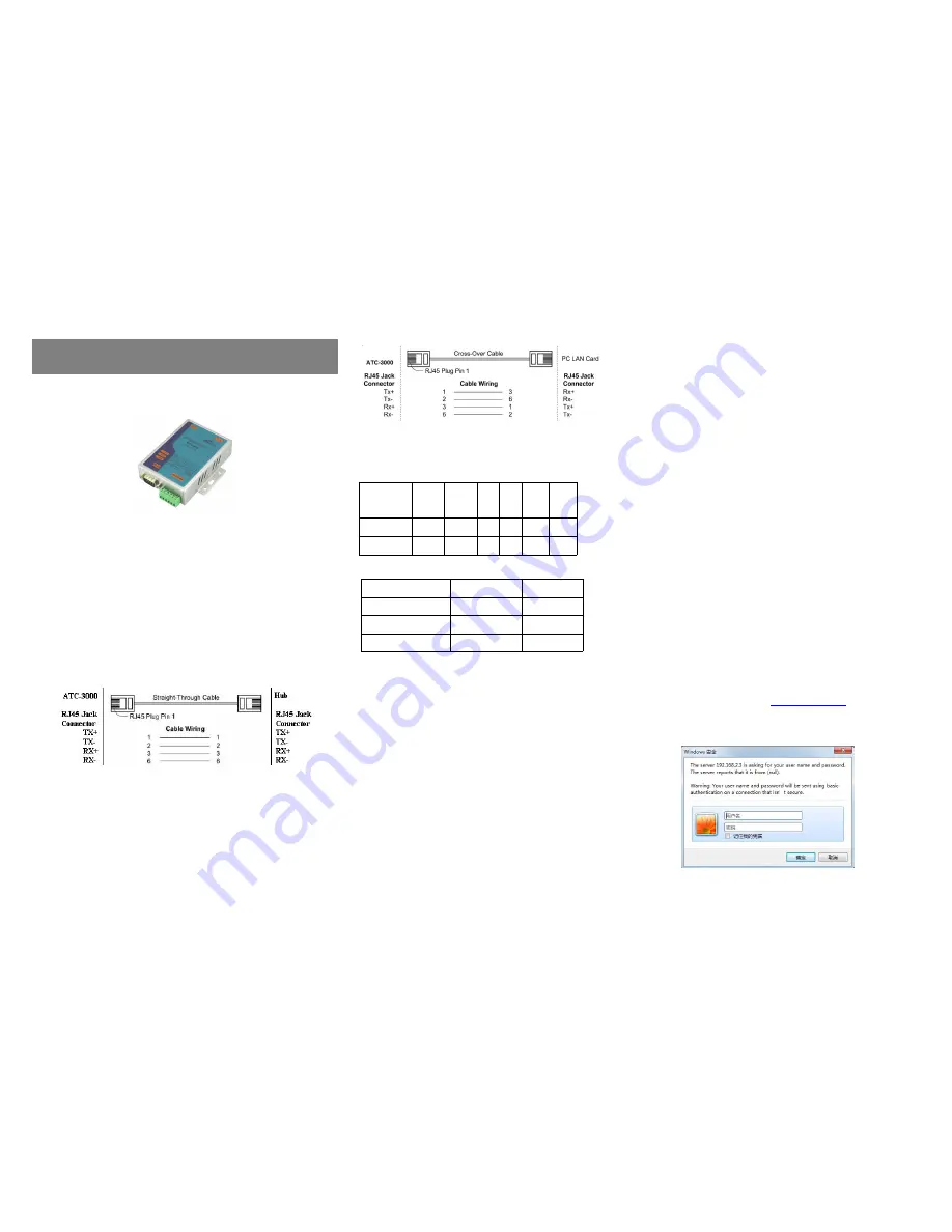
Connect an Ethernet cable to ATC-3002 unit if connecting to a
switch or cross-over direct to the PC as Figure 1.
Figure 1
■
ATC-3002 10/100 Port t connect to Ethernet card use
coss-Through Cable as Figure 2.
Figure 2
RS-232 Pinout
:(
DB9 Male)
RS-422/485 Pinout
:(
Six Terminal from left
)
■
Connect the power adapter to ATC-3002 and
other
apply
power.
Power
from
other
device.(+9--+48V).
3
3
.
LED indication
LINK ——
Ethernet interface right light, indicating
Ethernet is established, the green light is
on behalf of the establishment, not bright
or bright yellow on the contrary;
ACT
——
Ethernet interface left light, blinking
between the Ethernet port and RS232 /
422/485 data transmission;
TXD ——
Blinks when data is sent by the Ethernet
port to the RS232 / 422/485 serial ports;
RXD ——
Blinks when data is sent by the RS232 / 422/485 serial
port to the Ethernet port;
PWR——
Power indicator, red light when the power is turned on.
4
4
.Software Installation
■None
5
5
.
Configure the ATC-3002
■
Use this section to set up your computer to assign it a static IP
address in the
192.168.2.1 to 192.168.2.254
range with a subnet
mask of 255.0.0.0. The default IP address of ATC-3002 is
192.168.2.3, the computer IP user can not set this value,
otherwise it will cause IP address conflict.
This is necessary to ensure that your computer can communicate
with your ATC-3002. Your computer must have an Ethernet card
and TCP/IP installed. TCP/IP should already be installed on
computer using Windows 98/2000/XP and later operating
systems.
■
Open your web browser and type
http://192.168.2.3
in the browser’s
address box
. This address is the factory set IP Address of your
ATC-3002. Press
“
Enter
”
.
Figure 3
Terminel
No.
1
2
3
4
5
6
RS-422
T+
T-
R+
R-
VCC
GND
RS-485
485+
485-
/
/
VCC
GND
(DB9 Male)
Signal
I/O
PIN2
RXD
IN
PIN3
TXD
OUT
PIN5
GND
-


