
Summary of Contents for PN 6000 S
Page 1: ......
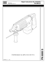
The Atlas Copco PN 6000 S user manual is a comprehensive repair instructions manual available for free download at 88.208.23.73:8080. Perfect for owners of this powerful product, it provides step-by-step guidance for maintenance and troubleshooting to ensure optimal performance and longevity. Get your free manual today.
Page 1: ......


