Figure 3
Tol/- 2 mm
HD16Lplus
HD16Pplus
HD16Splus
HD16Hplus
Product code
313 mm
313 mm
766 mm
610 mm
[A]
331mm
1079 mm
634 mm
790 mm
[B]
Figure 4
COUPLER
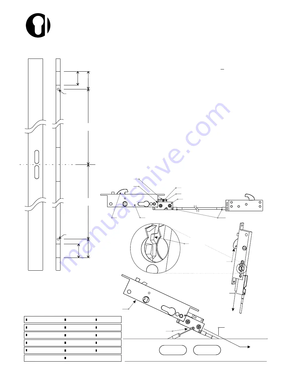
Door Cutout (Figure 1)
1
Prepare the cutouts in the section using the diagram and chart.
NOTE:
ADHERE TO THE DIMENSION TOLERANCES
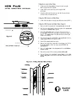
Installing the BOTTOM Lock (Figures 2 & 3)
1
Attach the bottom lock assembly
drive box
to the
HD8 centre
lock
, ensure the
coupler
fits over the
location pins
(Figure 2).
NOTE:
place a support directly beneath the couple and slide.
Fasten the
coupler
in place doing both or either of the following:
a) Fit the #6x6mm screw supplied (if applicable).
b) Firmly rivet over both location pins.
2
Unlock the lock by pressing on the
rocker arm
and pulling the
slide
down from the centre lock until it stops (Figure 3).
NOTE:
to assist in preventing locking while assembling, retract
the
main beak
.
3
Select the bottom lock/centre lock assembly. Slide it down into
the section via the centre lock cutout, leaving the centre lock out of
the section.
Installing the TOP Lock (Figures 4 & 5)
1
While holding the centre lock aside, slide the top lock into the
section and hook the
drive wire
into the remaining wire hole in
the
drive box coupler
(Figure 4).
2
Carefully guide the whole assembly into the section, then using a
screwdriver, clip the
collar lugs
into the
drive box
. (Figure 5
over page)
NOTE:
Ensure that the
collar lugs
are firmly in place.
Figure 1
46 mm
46 mm
[B] +/- 2mm
75 mm
75 mm
Æ
10 mm
Æ
10 mm
[A] +/- 2mm
HOOK THE DRIVE BOX
ONTO THE LOCK BODY
PUSH LOCK TO THE SIDE WHEN
FITTING THE TOP REMOTE
FIT THE TOP REMOTE
DRIVE WIRE TO THE
REMAINING WIREHOLE
SLIDE THE BOTTOM LOCK
ASSEMBLY INTO THE
SECTION FIRST
PULL THE
SLIDE DOWN
RETRACT MAIN BEAK
TO ASSIST INSTALLATION
PRESS THE ROCKER
ARM DOWN
Figure 2
BOTTOM LOCK ASSEMBLY
HD8 CENTRE LOCK
COUPLER/SLIDE LOCATION PIN X 2
COUPLER FIXING SCREW
MAIN BEAK
DRIVE BOX
HD16 Plus Instructions 04.cdr
HD16 PLUS
Fitting instructions


