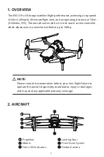
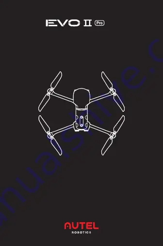
background image

QUICK START GUIDE

V3

Summary of Contents for EVO II Pro V3

Page 1: ...QUICK START GUIDE V3 ...

Page 2: ...C The aircraft comes with a 6 4 inch touch screen controller which allows users to view the live feed at up to 1080p NOTE Please read all documentation before your first flight Failure to operate the aircraft responsibly could lead to injury or damages and may void any applicable warranty coverage Propellers Motors Front LED Indicators Landing Gear Front Vision System Gimbal Camera ...

Page 3: ...2 Power Button Rear Vision System Left Side Vision System Rear LED Indicators SD Card Slot Right Side Vision System Aircraft Battery Air Vent USB C Port Pairing Button Pairing Indicator ...

Page 4: ...3 Ultrasonic Sensor Downward Vision Lighting LED Downward Vision System Upward Vision System ...

Page 5: ...lor Definitions of Indicator Status Normal RGY Alternate Flashing System self test is activated YG Alternate Flashing The aircraft is warming up G Slow Flashing The aircraft is in GPS mode Warning Y Slow Flashing The aircraft is in ATTI mode Y Fast Flashing No connection between the aircraft and smart controller R Slow Flashing Low Battery Warning R Fast Flashing Critically Low Battery Warning R S...

Page 6: ...stomizable Button Chest Strap Hook Power Button Antenna Microphone Air Outlet USB A Port USB C Port Micro SD Card Slot Touch Screen Auto takeoff RTH Button HDMI Port Record Shutter Button Zoom Control Wheel Right Control Stick Pause Button Battery Level Indicator ...

Page 7: ... to fully charge the aircraft battery and controller Aircraft Battery Plug the charging connector into the battery s charge port and connect the other end to power adapter Plug the power adapter into a power outlet 100 240V Controller Connect the USB C cable to the USB C port at the top of the controller and the other end to power adapter Plug the power adapter into a power outlet 100 240V 1 2 ...

Page 8: ...r from Google Play and install the app on your controller NOTE Power off the aircraft before folding the arms Fold in the rear arms and propellers first and then the front ones 1 Before powering on the aircraft please remove the gimbal guard 2 Unfold the arms and propellers ...

Page 9: ...hing the Propellers NOTE Power off the aircraft before attaching or detaching propellers Propellers must be undamaged and firmly attached 1 Power off the aircraft 2 Pair the propellers and corresponding motors according to the white mark 3 Press each propeller down firmly and rotate in the lock direction to securely attach the propeller 1 Power off the aircraft 2 Press each propeller down firmly a...

Page 10: ...w them into the corresponding bases 2 Unfold the antennas When the antenna and the back of the controller are at an angle of 180 or 270 and the antenna surface is facing the aircraft the signal quality between aircraft and controller will reach the optimal condition 1 Press and hold the power button for 2 seconds to turn on the controller 180o 270o ...

Page 11: ...ks for two seconds as shown below 2 Push the left command stick slowly upward 11 TAKE OFF NOTE The default control stick mode is mode 2 The left stick controls the altitude and heading of the aircraft while the right stick controls the forward backward and sideward movements Before takeoff place aircraft on a level surface stand well clear of the rear of the aircraft or ...

Page 12: ...ommand Stick Left Side View Left Side View Top View Rear View Top View Rear View Left Side View Left Side View Ascend Forward Nose Rotates Left Left Right Nose Rotates Right Descend Backward Upward Upward Move Left Move Left Move Right Move Right Downward Downward ...

Page 13: ...n Power EIRP 900MHz FCC ISED 31dBm 2 4GHz FCC ISED 32dBm CE MIC SRRC RCM 20dBm 5 8GHz 5 7GHz FCC ISED SRRC MIC 33dBm CE RCM 14dBm Remote Controller Operating Frequency 902 928MHz FCC 2 4 2 4835GHz 5 725 5 850GHz Non Japan 5 650 5 755GHz Japan Transmission Power EIRP FCC 33dBm CE 20dBm 2 4G 14dBm 5 8G 5 7G SRRC 20dBm 2 4G 33dBm 5 8G 5 7G ...

Page 14: ...ts are designed to provide reasonable protection against harmful interference in a residential installation This equipment generates uses and can radiate radio frequency energy and if not installed and used in accordance with the instructions may cause harmful interference to radio communications However there is no guarantee that interference will not occur in a particular installation If this eq...

Page 15: ... guidelines when used with an accessory designated for this product or when used with an accessory that contains no metal For body worn operation this device has been tested and meets the FCC RF exposure guidelines when used with an accessory designated for this product or when used with an accessory that contains no metal and that positions the device a minimum of 10mm from the body ISED Specific...

Page 16: ...ctionnement du corps usé cetappareil a ététesté et répond aux lignesdirectricesd exposition RF ISEDC lorsqu ilestutilisé avec un accessoiredésigné pour ceproduitoulorsqu ilestutilisé avec un accessoire qui ne contient pas de métal etqui positionnecet appareil à au moins 10mm du corps EU UK Compliance Autel Robotics Co Ltd hereby declares that this wireless device is in compliance with Directive 20...

Page 17: ...16 www autelrobotics com 2022 Autel Robotics Co Ltd All Rights Reserved ...

Reviews: