background image


Carony Go

Carony Drive 


Safety
General
Service and 
maintenance
Mechanics

Service manual

(Discontinued)

Summary of Contents for Carony Drive

Page 1: ...Carony Go Carony Drive Safety General Service and maintenance Mechanics Service manual Discontinued ...

Page 2: ......

Page 3: ...rvice manual 1 Service check ups 1 2 Instructions for service and maintenance 1 3 Updates 2 1 Description 2 2 Exploded views and components 2 3 Trouble shooter 2 4 Repair manual 0 Technical data 3 1 Description Programming 3 2 Wiring diagrams 3 3 Trouble shooter 3 4 Repair manual ...

Page 4: ...4 ...

Page 5: ...he ground lead when removing a bat tery And also connect the ground lead last when fitting bat teries Do not connect a discharged battery in series with a charged one It can cause the batteries to explode Do not wear metal objects like rings and wristwatches Even a small voltage can produce high current and can cause burn injuries Always cover the top of the battery with a rag or other non conduct...

Page 6: ...6 ...

Page 7: ...nsion front wheels 200x50 mm Tyre pressure front wheels 2 6 bar Dimension rear wheels 315x50 mm Tyre pressure rear wheels 2 8 bar Range 25 km Max speed 6 5 km h Max reverse speed 3 km h Braking distance 0 8 m Obstacle clearence 6 cm Turning space180 degrees 150 cm Hill climbing ability 6 grader Max user weight 120 kg Battery type AGM 1245 Batteriy max dimension 198x 165x170 Main fuse 50 A Carony G...

Page 8: ... sill Carony rails and seat Carony rails Turnout Carony rails BEV seat Turnout Carony rails Bev seat A B C D E F 950 mm Measured from where the sill moulding starts to bend upwards 830 mm 630 mm 650 mm Max 375mm 425mm with raising kit Measured from ground to vehicle sill 600 mm 0 1 Technical data 840 mm vehicle sill ...

Page 9: ...o bend the neck needs more space This can up to a certain point be compensated by inclining the backrest a little bit 1000 mm Measured by penulating by the approximate point of Turnys height including the seat 750 mm Measured by the ultimate out shooting point of the dashboard 650 mm Minimum leg space Turny 395 max 587 mm or Turny 300 max 492 mm E Carony Go Measurements for TURNY applications ...

Page 10: ...10 0 1 Technical data ...

Page 11: ...12 4 Front tyres 2 6 bar Rear tyres 2 8 bar 5 Tighten drive motors see page 12 or method 2 4 1 step 1 3 Switch the power on and check 6 Electrical functions 7 Seat adjustment 8 Speed limit when seat raised 9 Battery indicator when charged 10 Reading fault codes Remove cover and check 11 Battery contacts possible oxidation 12 Check battery voltage 13 Check cables and connector Every 12 months 14 Ch...

Page 12: ...onths service Motor release If the motor release is not working as it should see method 2 4 4 Change of transversal release shaft Check if any of the joints or bars are broken Control unit arm lock unlock in the position chosen If the joystick arm doesent lock in the position chosen the cause is most probably a defect gas spring or release lever See method 2 4 12 Joystick arm release change incl a...

Page 13: ...vice the spring shall be changed Spare part kit Art No 418097 leaf spring See method 2 4 5 Change of docking mechanism Carony Go The wires on both sides shall be adjusted to make the release levers affect the docking mechanism directly Adjust release wire for docking mechanism Carony Go Adjust at front or at the back ...

Page 14: ...er Replacing the tube Place pieces of board under all wheels except the one that shall be amended Remove the rear wheel by using a 17 mm wrench Remove the front wheel by using a 6 mm hexagon key and a 13 mm wrench Let the air out of the tube and remove the tyre from the rim Replace the old tube with a new one Restore and mount the wheel Don t forget to tighten the nut Inflate the wheel to specifie...

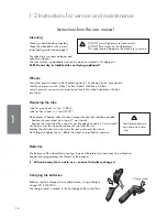
Page 15: ... bulb and replace it with a new Remount and tighten all screws Replacing bulbs of rear light and rear indicator Unscrew and remove the glass from the rear light Change bulb and remount the glass Replacing bulb of front indicators Use a blunt knife or other tool to remove the glass Replace the bulb and remount the glass 1 2 Instructions for service and maintenance Replacing the batteries Always rep...

Page 16: ...8 the Control Unit Protection will be updated From Mrch 2008 there is a new release lever without a lock pin Control unit protection A hexagon lock screw is used instead Method 2 4 1 step 10 Release the lock screw and lift it up ...

Page 17: ...pecification for the right pressure The height adjustment is mechanically driven by one electrical motor and four Ketter pillars consisting of an angled gearbox and a screw The lift system has a micro switch mounted in one of the Ketter pillars this will pro vide the power module with information about the height in order to slow down the wheelchair if the seat is not at its lowest position The pr...

Page 18: ...18 2 2 2 Exploded views and components Carony Go wheel unit 1 15 2 27 14 21 13 3 17 26 25 18 24 11 23 16 5 49 47 22 48 7 4 22 6 28 45 42 46 44 43 31 30 32 39 33 40 12 34 36 20 37 50 38 35 41 ...

Page 19: ... Washer BRB 17x30x3 fzb 412959 p o t p a C 1 9 2 4 6 7 7 1 4 7 5 1 1 0 0 r a e r p a C 1 8 2 27 2 Column rear 417424 26 4 Plug screw Ø6 L 11 0 417832 25 4 Screw MC6S M4 x 35 417809 24 2 Screw MK6S M6 x 16 414079 23 2 Locking nut M6LM M6 412305 22 10 Screw MK6S M5 x 10 416744 21 6 Screw MK6S M6 x 12 414079 20 2 Tapping screw 4 2x25 418177 Berner 723851 19 1 Wing nut DIN 315 M6 417806 18 1 Lifting m...

Page 20: ...20 2 2 Exploded views and components Carony Drive footrest system DISCONTINUED 1 2 6 8 22 7 20 4 5 9 3 14 16 15 17 13 16 21 17 18 14 11 12 19 17 15 10 ...

Page 21: ...214 Footrest 1 5 M36 0028 419229 Chairplate 1 6 M36 0003 419234 Slide rod bracket 1 7 M36 0021 419235 Axel 1 8 GFM 1214 15 419218 Glide bushing 1 9 ISO 7380 416359 Screw M8x40 1 10 ISO 7380 412747 Screw M8x12 4 11 ISO 7380 411345 Screw M8x16 4 12 DIN 7991 419239 Screw M6x16 2 13 DIN 125 A 6 4 412300 Washer 6 4x12x1 6 8 14 DIN 125 A 8 4 412332 Washer 8 4x16x1 6 2 15 DIN 934 M6 413038 Nut M6 8 16 DI...

Page 22: ...22 2 2 Exploded views and components 2 Carony Go foot rest 3 4 2 5 6 7 1 3 4 5 2 6 7 1 ...

Page 23: ... Wing screw 412186 3 1 Tube fittings Ackurat 22x19 28 32S 418176 2 1 Footrest left 416562 1 1 Holder foot rest weld assy 001040 417982 7 1 Included in fig 6 6 1 Foot heel support 100630 5 1 Included in fig 2 4 1 Wing screw 412186 3 1 Tube fittings Ackurat 22x19 28 32S 418176 2 1 Footrest right 416561 1 1 Holder foot rest weld assy 001040 417982 2 2 Exploded views and components Component list for ...

Page 24: ...24 2 2 2 Exploded views and components Carony Go Drive anti tip 3 10 7 6 4 11 1 9 5 8 2 12 2 10 6 7 3 4 1 8 9 5 11 12 ...

Page 25: ... 1 4 2 2 1 1 0 0 t f a h S 1 6 5 0 3 4 1 4 l e e h W 2 5 5 9 9 7 1 4 1 2 1 1 0 0 t l o b k c o L 1 4 3 1 Bracket left 001120 417994 2 9 1 3 N G 0 4 6 1 1 4 e l d n a H 1 2 1 1 Anti tip left weld assy 001116 417984 Ä 12 2 Screw MK6S M6 x 12 414079 11 1 Spring SF TF 1552 SS1774 04 418180 10 2 Washer 6 4x12x1 6 412300 3 0 3 4 1 4 6 Ø k c o l a 2 9 8 1 Shaft wheel 60 240 414465 6 9 9 7 1 4 2 2 1 1 0 0...

Page 26: ...26 2 2 2 Exploded views and components Carony Go Drive lever system 1 2 4 9 7 5 6 8 10 11 3 ...

Page 27: ... 4 1 1 10 2 Shims 12x18x0 5 415716 9 1 Screw MK6S M6 x 12 414079 8 1 Washer 7x35x2 SRKB fzb 417804 7 2 Locing nut M6LM M12 412984 6 2 Locking nut M6LM M8 413232 5 2 Screw MC6S M8 x 80 416585 4 2 Front wheel Ø175 412193 3 2 Alu front forks 151mm MBL 418084 2 2 Slide bearing COB010F FS 1F 2515 418163 1 1 Lever arm weld assy 001032 417985 ...

Page 28: ...28 2 2 2 2 2 Exploded views and components Carony Go Drive joystick arm system A A 1 2 B 0 30 1 A A B 6 11 22 8 12 13 3 23 7 24 20 27 21 2 1 9 10 25 28 31 32 33 34 29 30 18 15 16 14 5 17 4 19 26 ...

Page 29: ... 0 t f a h S 1 1 2 1 6 7 7 1 4 8 2 0 1 0 0 t h g i r p a C 1 0 2 19 1 Latch right 001030 417970 18 1 Protection device 001200 417990 17 1 Joystick Shark 417416 16 1 Spacer latch 001273 417991 15 2 Screw MC6S M4 x 10 417731 14 1 Hinged bracket right 417972 13 1 Slide bearing COB010 FS 1 1412 418161 12 1 Slide bearing COB010F FS 1F1417 418160 1 0 3 4 1 4 8 Ø k c o l a 4 1 1 10 2 Screw MF6S M5 x 8 41...

Page 30: ...30 2 2 2 2 2 Exploded views and components Carony Go Drive motor release handle left 18 12 11 19 5 14 10 4 13 9 7 6 8 21 22 24 25 23 22 3 26 20 15 16 2 17 1 ...

Page 31: ...7 2 Retaining ring DIN 6799 8 418158 16 2 Slide bearing Iglidur clip 2 MYM 10 10 418142 1 4 1 8 1 4 9 5 3 1 0 0 k c o l 2 5 1 14 1 Tension pin FRP 3 x 20 412585 13 1 Screw MC6S M6x45 414237 12 1 Release knop 001049 417978 2 5 9 7 1 4 8 4 0 1 0 0 t e k c a r B 1 1 1 10 1 Adjusting lever left 001047 417976 9 1 Bracket left 001046 417974 8 2 Thread rod M5 L 35 M4171 7 1 Thread rod M5 L 110 M4170 6 6 ...

Page 32: ...32 2 2 2 2 Exploded views and components Carony Go rails 5 7 4 3 9 10 8 11 12 1 2 6 13 9 11 2 8 10 12 4 1 7 3 6 5 13 ...

Page 33: ... 5 4 9 1 2 1 4 7 0 1 0 6 g n i s u o H 1 4 3 2 Slide bearing COB010F FS 1F 0608 418162 2 1 Release handle left weld assy 001297 418001 1 1 Slide bar left weld assy 001053 417981 Ant Benämning Material Mod nr Ämne Dimension Anm Art Nr Det nr 13 1 Washer BRB 6 4x12x1 6 FZB 412300 12 1 Spring plate 001261 418097 11 2 Screw MF6S M6 x 20 417042 10 1 Tension pin FRP 3 x 12 412585 3 0 0 8 1 4 7 6 0 1 0 0...

Page 34: ...34 2 2 Exploded views and components Carony Go Drive seat and armrests 1 8 7 6 3 5 2 10 9 4 ...

Page 35: ...r 10 1 Arm rest left Inkl screw and washer 417847 9 1 Arm rest right Inkl screw and washer 417846 8 2 Washer BRB 6 4x16x1 5 FZB 415511 7 2 Screw MK6S M6 x 12 414079 6 4 Screw MK6S M10 x 50 412226 7 0 0 8 1 4 4 5 1 1 0 0 r e c a p S 2 5 4 2 Bracket weld assy 001294 418006 5 0 0 8 1 4 2 5 1 1 0 0 t e k c a r B 2 3 4 0 0 8 1 4 3 5 1 1 0 0 r e c a p S 2 2 0 2 4 0 0 1 r i a h C 1 1 ...

Page 36: ...Adjustment or change of linkage for the motor release Check transversal release shaft or motor transmission Linkage for Carony Drive footrest system is loose or needs adjusting Ketter pillar bushings are worn out Adjust lock lever for the gas spring or replace it Change the arm attachment Change brakes or motors Check tyre pressure Check release linkage SYMPTOM MEASURE METHOD Lift motor 2 4 10 or1...

Page 37: ... Go replace 2 4 7 Rear Ketter pillar of Carony Drive replace 2 4 8 Front Ketter pillar of Carony Go replace 2 4 9 Front Ketter pillar of Carony Drive replace 2 4 10 Lift motor Carony Go replace 2 4 11 Lift motor Carony Drive replace 2 4 12 Joystick arm release replace incl adjustment and change of gas spring 2 4 13 Docking mechanism wire replace 2 4 14 Anti tip replace 2 4 15 Footrest rails for Ca...

Page 38: ...ance under the chassis 2 Set the motor release lever in drive position Remove the hub cap 3 Remove the wheel nut by using a 17 mm socket wrench 4 Remove the wheel Fix the wedge to the motor axle with a tape 5 Release the pin lock from the ball joint of the motor release mechanism 6 Loosen the ball joint ...

Page 39: ...he three screws that fix the motor by using a 4 mm hexagon key 9 Lift out the motor 10 If the motor needs to be replaced push out the small pin of the release lever and dismount the spring and the lever 11 If the brushes need to be replaced you can keep the release lever mounted Unscrew the brushes and replace them with new ...

Page 40: ...uction acording to 2 4 1 Replacing and servicing the motor on the right side Fig 1 7 8 Remove the batteries according to the User Manual 7 Remove the screw that fixes the motor release lever and remove the lever 8 Cut the bundle band holding the cable 9 Unscrew the three hexagon screws for the motor ...

Page 41: ...the compartment to run free 11 If the motor needs to be replaced pusch out the small pin for the release lever and dismount lever and spring from the old motor 12 If the coal cinders need to be replaced the lever can remain mounted Dismount the brushes from te holders and replace them with new 13 Remount the motor in reversed order NOTE Run the cable through the slit and do not forget to fix it to...

Page 42: ...2 Unscrew the hexagon screws holding the thrust plate Remove the thrust plate Use a solder pen to heat them before trying to loosen them it will save the Loctite 3 Remove the friction lining clean it wipe it off or replace it with a new if required 4 Remount the thrust plate This can only be mounted in one way Mount the motor cover and the motor according to instructions 2 4 1 and 2 4 2 ...

Page 43: ... the ball joint on both sides instruc tions 2 4 1 fig 5 and 6 2 Unscrew the two M4 screws that fix the clip bearings 3 Lift out the transversal release shaft 4 The clip bearings may now ne replaced 5 Mount the new in reversed order Adjust the linkage so that both wheels are released at the same time ...

Page 44: ...sm Carony Go 1 Remove the seat Take away the plug from the wire hole by using a flat tool 2 Unhook the wire from the hole 4 Dismount the plate spring behind the docking mechanism 3 5 Locate the pin that holds the axle for the cup 6 Knock away the pin by using a 3 mm drift ...

Page 45: ...45 2 DOCKING MECHANISM 2 4 Repair manual 7 The tension pin 9 Remount in reversed order and make sure to use a new pin 8 Press out the axle for the cup The spring shall be changed every 12 months ...

Page 46: ...ver 1 Remove the seat and pull away the top cover Unscrew the 4 hexagon screws of the Carony rails 2 Put the rails aside and loosen the cable chain 4 Cut away the bundel bands from both of of the Ketter pillar rubber housings 5 Unscrew the two screws holding the Ketter pil lars 6 Unscrew the two screws of the lift motor at tachment Rear pillars Art No 417424 ...

Page 47: ...amaged pillar with a new 8 Make sure to get the upper part of the new Ketter pillar facing towards the correct position to fit the Carony rail when remounting Do not forget to place an o ring to lock the hexagon rod 9 Be extremely careful to get the same height of the new Ketter pillar shall not differ more than 1 mm compared to the others Uneven pillar heights causes damage Make sure to measure f...

Page 48: ...e Loosen the cable chain 2 Remove the nut from the balljoint attachment for the footrest system 3 Unscrew the entire Carony Drive unit from the Ketter pillars 4 screws 4 Dismount the batteries according to method 3 4 1 Remove plastic cover by pulling the bot tom edge Disconnect possible rear light cables 5 Place the Carony on one side and remove the botton cover 6 Unscrew the screws holding the Dr...

Page 49: ...gon rods one at a time to allow removal of the damaged pillar Replace the damaged pillar with a new 11 Make sure to get the upper part of the new Ketter pillar facing towards the correct position to fit the Carony rail when remounting Do not forget to place an o ring to lock the hexagon rod 12 Be extremely careful to get the same height of the new Ketter pillar shall not differ more than 1 mm comp...

Page 50: ... rails 2 Put the rails aside and loosen the cable chain 5 Unscrew the two screws holding the Ketter pil lars 10 Pull the pillars slightly outwards unil the hex agon rod can go free Cut away the locking of the hexagon rod Pull away the hexagon rods one at a time to allow removal of the damaged pillar Replace the damaged pillar with a new 4 Cut away bundle band from rubber housing of the the Ketter ...

Page 51: ...hing which might be differently mounted Follow the instructions of method 2 4 7 Change of REAR ketter pillar of Carony Drive Use the instructions from 1 3 Do NOT remove rear cover or disconnect batteries pic 4 Pic 5 Just remove the plastic cover NOT the DriveLoc plate Proceed from pic 8 through to pic 12 11 Make sure to get the upper part of the new Ketter pillar facing towards the correct positio...

Page 52: ...top cover Unscrew the 4 hexagon screws of the Carony rails 2 Put the rails aside and loosen the cable chain 4 Unscrew the two screws holding the Ketter pil lars 5 Unscrew the two screws of the lift motor at tachment 6 Pull the pillars slightly outwards unil the hexagon rod can go free Cut away the locking of the hexagon rod Pull away the hexagon rod enough to remove the lift motor ...

Page 53: ...n o ring to lock the hexagon rod 2 4 11 Replace lift motor of Carony Drive Follow the instructions according to 2 4 7 Change of REAR Ketter pillar of Carony Drive Use the instructions from 1 9 Then follow the instructions from pic 6 through to 8 according to 2 4 10 Change of Lift motor on Carony Go ...

Page 54: ... 3 Remove the release head by first removing the ball of the release lever 4 Unscrew the locking screw that is placed underneath the joystick The dismounting will be easier if you first compress the gas spring 5 10 mm fold the arm slightly and lock it 5 Place the arm with the inner side facing up To be able to remove the A lock washer from the pin it is easier if you first use a centre punch and a...

Page 55: ... 1 and 3 4 turns further Direct the gas spring in line with the release head and lock it with the counter nut Now the gas spring is ready to be remounted REMOUNTING 7 Place the completed gas spring in the right position and fix it with a pin Place the arm so that the pin holds on to the side where the A lock is then beat in a second pin 8 Compress the gas spring 5 10 mm Mount the arm onto the arm ...

Page 56: ...wire from the lock head 2 Remove the outer nut of the wire adjustment from the rail 3 Remove the outer nut also from the front wire adjustment 4 Twist out the z formed end piece from the arm 5 Mount a new wire in the reversed order Note how the wire runs by the rear pillar 6 Adjust until there is no play DOCKING MECHANISM ...

Page 57: ... lock washer on one side and pull out the pin 2 Protect the handle with a piece of cloth Remove the handle by unscrewing it using a pair of universal pliers 3 Remove the lock head and the spring Clean and grease the spring and the lock head 4 Remount in reversed order ...

Page 58: ...nit until the rear rail screws are reachable 2 Start by unscrewing the rear screw of the rail that needs changing 3 4 Adjust the height to be able to unscrew also the front screw 5 Locate the bolts from underneath and unscrew them The bolts have loose welded nuts inside the rail so there is no need for a key 6 Now you can press the rail backwards to remove it ...

Page 59: ...59 2 2 4 Repair manual FOOTREST RAILS 7 This is what has been removed 8 When remounting place the weded nuts inside the rail when the rail is in position Screw in reversed order Check the function ...

Page 60: ...ws from underneath and remove the seat 2 Carony Drive Remove the fottrest system unit from the Ketter pillars by dismounting the link and unscrewing the 4 srews Carony Go remove the Carony rails 3 BE CAREFUL with the cable chain from the joystick arm it can easily be damaged 4 Cut away the bundle band that fixes the rub ber housing and remove this 5 Drill out the pop rivet ...

Page 61: ...ir manual KETTER PILLAR BUSHINGS 6 Carefully remove the bushing by using a tool 7 Tap down the new bushing in level with the pipe by using a plastic hammer 8 Drill a new hole in the bushing and mount a new pop rivet ...

Page 62: ...62 22 ...

Page 63: ...ing it down for four seconds the Carony Go will enter lock mode to turn the Carony Go on again press the horn button twice DRIVING SPEED To increase speed press Hare for decrease press Turtle The speed is set to 20 intervall but can be changed for more precise speed Press both hare and turtle buttons at the same time than you can adjust the speed in small units by holding the respectively buttons ...

Page 64: ...nd that the bat tery is sufficiently charged SEAT FUNCTION The Carony go uses only seat function number one Pressing this button means that you can move the seat up and down Avoid end positions to pre vent overload for the lift motor 1 2 HEAD LIGHTS Option If the Carony Go is equipped with lightnings this is the button to turn the front and rear lights on Pressing the button again will turn the li...

Page 65: ...for 4 seconds The display will turn off immediately After 4 seconds all LED s will flash briefly and the horn will sound a sharp beep The power will then turn off When the control unit is locked press the power button to turn it on All LED s will flash briefly The Battery Gauge LED s will then perform a slow right to left chase Press the Horn button 2 times before the countdown is completed approx...

Page 66: ...o operating voltage 18 24 27 V Carony Go Current 0 0 35 35 A Boost Current 0 0 15 15 A Boost Current time 0 0 10 10 s Idle Current 120 mA Seat Current 0 6 12 A Light feeding 24 V Drive motor 0 0 230 230 W Drive motor cont current 8 A Drive motor resistance 250mOhm Ohm Short Circuit Current Control 8 15 mA Because there is only one main fuse 50 A the Carony Go is equipped with a short circuit contr...

Page 67: ... up Attendance drive ATTENDANCE DRIVE Option The attendance drive makes it possible for the care giver to oper ate the Carony Go You can switch between user mode and attendant mode The speed poten tiometer adjust the overall speed response of the chair Adjust it depending on the speed you want to travel in depending on the walking speed of the care giver 3 3 3 1 Description and programming ...

Page 68: ...als responsability to ensure that the user is capable both of cognitively understanding and physically operating the programmed features With inappropriate programming settings certain features and options may not be acces sible or perform as expected Introduction All SHARK systems are fully programmable to provide superb performance for a wide variety of powerchair configurations or users All pro...

Page 69: ...e joystick full revere and the speed clock fully clockwise Sets how quickly Carony Go Drive will accelerate when the joystick is moved to reverse from neutral Sets how quickly Carony Go Drive will decelerate when the joystick is moved towards neutral from a reversed position The maximum speed Carony Go Drive will turn with the joystick full left or right and the speed pot fully clockwise Sets how ...

Page 70: ...er Defines the amount of assistance SHARK provides in controlling the chair when a Stability Profile with Chair tamer is selected effectively amplify ing the effect of the Stability Profile Set to 0 for no modification of the Stability Profile with higher values providing increasing assistance to keep the chair stable and safe When resetting please refer to the Flow Chart Service and Configuration...

Page 71: ...etimes in other menues change the written language Program View edit Attendant exit next yes Go to page 2 for programming wheelchair And page 3 for attendant programming This menu depends on if the attendant drive is activated Attention Changing in values will effect certificates of the wheelchair Tech for technicans only and a code most be used to enter Page 1 Here you can change to short or very...

Page 72: ...g 40 exit next down up No chair tamer Traction 0 exit next down up No chair tamer Stability profile No chair tamer exit next swap No chair tamer Load compensation 100 mOhms exit next down up All exit buttons will take you back to Dynamic Shark menu on page 1 Possible value is 0 100 in 5 step Possible value is 0 90 in 5 step Possible value is 30 100 in 5 step Possible value is 0 100 in 5 step Possi...

Page 73: ... next down up Attendant Turn acceleration 40 exit next down up Attendant Turn deceleration 60 exit next down up Attendant Tremor damping 40 exit next down up No chair tamer Traction 0 exit next down up All exit buttons will take you back to Dynamic Shark menu on page 1 Possible value is 0 100 in 5 step Possible value is 0 90 in 5 step Possible value is 30 100 in 5 step Possible value is 0 100 in 5...

Page 74: ...O 1 3 Lift Motor Headlight Optional Lights Tail lights LR RR RF LF GN 0 75 BL 1 3 LB 0 75 GN 0 5 Y 0 75 R 0 75 GN 0 5 WT 2 0 R 4 0 SB 4 0 WT 2 0 Brake LEFT RIGHT Brake WT 2 0 R 6 0 SB 6 0 WT 2 0 R 4 0 SB 4 0 Height switch 50 A 3 2 Wiring diagram ...

Page 75: ...green orange grey red black violet white yellow pink blau braun grün orange grau rot schw violet weiss gelb rosa bleu brun vert orange gris rouge noir violet blanc jaune rose azul marrón verde naranja gris rojo negro violeta blanco amarillo rosa blu marrone verde arranc grigio rosso nero viola bianco giallo rosa ...

Page 76: ...nicians In some cases viewing a history of any abnormal conditions that occurred previously on the system may be useful in diagnosting the current condition This can be done by entering the Fault Log from the Diagnostics menue Usage statistics are also available from this menue DYNAMIC Wizard Wizard is the preferred diagnostics tool in the workshop environment providing a full fault his tory and v...

Page 77: ...nit Troubleshooting strategies When a symptom or malfunction is detected the basis for troubleshooting is basic data collection Customer information Dealer information Specifications use the hand held programmer o Serial nr o Machine hours o Model year Flash codes Description of malfunction or symptom Describe the problem When did the problem occur What happened just before the problem Lead and co...

Page 78: ...mal and try again 02 Battery fault Check batteries and cables Try changing the batteries 03 Left Motor fault Check the left motor cables and connections 04 Right Motor fault Check the right motor cables and connections 05 Left park brake fault Check the left park brake cables and connections 06 Right park brake fault Check the right park brake cables and connections 07 SHARK Control Unit fault Int...

Page 79: ...k the control unit Voltage too high or too low Check the batteries and the cables Batteries may be empty charge the batteries Batteries may be overcharged if driving downhill slow down Batteries may be damaged replace the batteries Short circuit Check the motor cables for damage Motor brushes may be too stiff bouncing against the case Replace motor brushes or motor Open circuit Check if the motor ...

Page 80: ...uit or broken Check the parkbrake cables for damage Attendant remote fault Check attendant remote cables for damage Disconnect and reconnect attendant remote If fault doesn t go away disconnect the attendant remote as a temporary solutution and contact Dynamic Internal fault Contact Dynamic Actuator fault Check the actuator and the acteuator cables Lighting fault Check the light bulb and the light...

Page 81: ...81 3 3 Repair manual 3 4 1 Batteries replace 3 4 2 Power module replace 3 4 3 Joystick dismount 3 4 4 Speedlimiter and height switch replace ...

Page 82: ...ts and turn the battery 90º standing up 3 Lift out the battery 4 Pull the remaining battery as far back as pos sible and lift it out Disconnect the cables in the two removed batter ies 5 Connect the cables to the new batteries and mount the new batteries in reversed order IMPORTANT Both batteries must be replaced at the same time Always replace batteries of the same type and brand ...

Page 83: ...t the batteries 7 Check the functions of the new power module 3 Lift up the power module as high as possible and disconnect the contacts from the bottom side The contacts counting from the left are joystick multi contakt motor right side battery contact and motor left 2 Unscrew the two screws fixing the power module 1 Disconnect the battery contact by the fuse holder ...

Page 84: ...K 1 Fold down the joystick arm and the joystick 2 Remove the two hexagon screws that hold the impact protection 3 Remove the two counter sunk screws Remove the joystick and the cable protection 4 Replace the joystick with a new and mount this in reversed order ...

Page 85: ...th a 2mm Allen wrench don t remove it just loosen it 4 Remove the switch by pulling it out Remount in reversed order and verify the function Make sure that you don t push the switch completely to the bottom because it will then hit the pillar when it travels Just push it inwards and release it mm or less then tighten it Measure the switch with an ohm meter In raised position it should be infinite ...

Page 86: ...86 Notes ...

Page 87: ...87 Notes ...

Page 88: ...Notes ...

Page 89: ...ort Centre CSC Tel 46 302 25440 Fax 46 302 25407 E mail support autoadapt com Autoadapt AB Åkerivägen 7 S 443 61 Stenkullen Sweden Tel 46 302 25400 E mail contact autoadapt com www autoadapt com www autoadapt de www autoadapt fr www autoadapt se ...

Reviews: