background image

A U T O M A T I C   T R A N S M I S S I O N   R E M O T E   S T A R T E R  

C O M B O   W I T H   F U L L   A L A R M   S Y S T E M  


AS-6010 TW-A


Installation Guide 

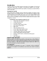
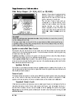
A note concerning the battery inside the transmitter: 

Depending on the usage of the transmitter, the battery can last anywhere between 3 to 6 
months.  When the battery is low, it the transmitter will emit two beeps in a repetitive 
cycle.  At that point you should replace your battery with a new one.  That is why we 
recommend that you keep a spare battery somewhere handy such as the glove 
compartment. 

Notice 

The manufacturer will accept no responsibility for any electrical damage resulting from improper installation of 
the product, be that either damage to the vehicle itself or to the Unit. This Unit must be installed by a certified 
technician using all safety  devices supplied. Please note that this guide has been written for properly trained 
Autostart technicians: a certain level of skills and knowledge is therefore assumed. Please review the 
Installation Guide carefully before beginning any work. 

Warning 

This System is designed for vehicles with an


automatic 

Transmission only. Before installing the Unit, 

test that the vehicle does not start when the Gear Select Lever is in the “Drive” position. If it starts in gear, 
install a manual-transmission remote starter system instead.


DOC:

.1.00  

 November 3, 2004 

Gp CA Lp 

Manufactured in Canada by Autostart 

Summary of Contents for AS-6010 TW-A

Page 1: ...y for any electrical damage resulting from improper installation of the product be that either damage to the vehicle itself or to the Unit This Unit must be installed by a certified technician using all safety devices supplied Please note that this guide has been written for properly trained Autostart technicians a certain level of skills and knowledge is therefore assumed Please review the Instal...

Page 2: ...i speed Tach Programming 13 Automatic Tach Programming 14 Siren or Horn Chirp Timing 14 Testing 15 Closing Up 15 Supplementary Information 16 Fifth Relay Output 2nd IGN ACC or CRANK 16 Caution 16 Ignition controlled Door Locks 16 Ignition Re lock 16 Secure Lock 16 Standard Secure Lock 16 Smart Secure Lock 17 Lock Pulse Duration 17 Engine Run Time 17 Open Zone Notification 17 Starter Kill Installat...

Page 3: ...rter and Alarm System Control Unit 1 Antenna Interconnect Cable1 1 Long range Transceiver 1 multi channel 5 button Remote Controls 1 plug in dual zone Shock Sensor 1 plug in L E D 1 high power 120 dB 6 tone Siren 1 six pin 14 AWG Harness Ignition Harness 1 five pin 18 AWG Harness Main Harness 1 twelve pin 22 AWG Harness Accessories Harness 1 two pin 22 AWG Harness Accessories Harness 1 parts bag a...

Page 4: ...onnections Keep the Antenna away from other types of antennas GPS OnStar Never install the control unit where it could interfere with normal operation or obstruct service technicians Always use a grommet when running wires into the Engine compartment Never run wires through bare or sharp metal Do not disconnect the battery on vehicles equipped with air bags and anti theft radios Never ground the c...

Page 5: ...uring the very last steps 6 Pin Main Ignition Harness Wire Colour Function Description A RED 12 V Battery Connect to the largest 12 V supply wire at the Ignition Harness Ensure that the OEM power wire is fused for more than 30 A B PURPLE Starter output 30 A Connect to the Starter wire of the vehicle The source wire should have 12 V with the Ignition Key in the CRANK position only C RED 12 V Batter...

Page 6: ...a constant output as long as the TRUNK button is held pressed for Sunroof or Window closure 2 BROWN Lock output Programmable 500 mA negative output 1 10 sec 7 10 sec or 4 sec pulse 3 GREEN Unlock output Programmable 500 mA negative output 1 10 sec 7 10 sec 4 sec or double 1 4 sec pulse ON 250 ms OFF 500 ms ON 250 ms 4 WHITE BROWN Rearm output 500 mA ground signal when the Doors are locked by remot...

Page 7: ...ler should use either the positive or the negative Door input Never use both of them simultaneously 12 YELLOW Glow Plug input In Diesel Mode this positive input will monitor the Glow Plug Light it will wait for up to 18 seconds until the Glow plug Light goes out before allowing the System to proceed to cranking the Engine Connect to the side of the Glow plug Light which is positive when the Light ...

Page 8: ...This 500 mA negative output can be programmed for one of the following Options 1 Constant wh ile the LOCK and UNLOCK buttons are pressed simultaneously 1 sec after the buttons are released 2 Pressing LOCK and UNLOCK simultaneously toggles the output ON and OFF with automatic toggle OFF after 30 seconds 2 YELLOW Parking Light output 500 mA negative Parking Light output Flashing the Hood Pin Switch ...

Page 9: ...ssing the Hood Pin switch in the Engine compartment Caution The Hood Pin switch must be installed and connected in order for the Programming Assistance Button to function The button will work only when the Hood is up Programming a Transmitter Before you Proceed The Transmitter of the System is not delivered pre programmed it must be programmed after the wiring of the System is completed The System...

Page 10: ...o exit close the Hood Table 2 Programming a Transmitter To program a Transmitter on the second vehicle for Multi car Operation you must press the TRUNK and LOCK buttons simultaneously instead of LOCK or UNLOCK in transmitter programming procedure Entering Programming Options Mode The System is equipped with three custom programming Modes that allow the installer to custom fit the system outputs ac...

Page 11: ...ON 3 Ignition UNLOCK ONLY OPTION 4 Ignition LOCK ONLY FUNCTION 2 Secure Lock OPTION 1 SecureLock DISABLED 1 sec Disarm pulse OPTION 2 Secure Lock ENABLED in Smart Mode OPTION 3 Secure Lock DISABLED 1 2 sec Disarm pulse OPTION 4 Secure Lock ENABLED in Standard Mode FUNCTION 3 Door lock pulse timing OPTION 1 7 10 sec Lock Unlock pulses OPTION 2 4 sec Lock Unlock pulses OPTION 3 7 10 sec Lock pulse a...

Page 12: ...Weather Mode OPTION 1 Diesel Mode with 20 minute Run Time in Cold Weather Mode OPTION 2 Gas Mode with 4 minute Run Time in Cold Weather Mode OPTION 3 Diesel Mode with 9 minute Run Time in Cold Weather Mode MODE 3 INDICATES DEFAULT SETTING FUNCTION 1 Siren or Horn Chirps OPTION 1 Warning Chirps OPTION 2 Full chirps ENABLED OPTION 3 Chirps ENABLED with Open Zone Notification Siren warning 10sec afte...

Page 13: ... of Tach signals produced by recent Ignition systems There is no necessary manual adjustment Nevertheless a Tach programming procedure must be carried out every time a new System Unit is installed This is because the Tach signals of certain Ignition systems are sometimes too low or too high for the System causing failed start ups at various temperatures 1 Flash the Hood Pin switch see Table 1 The ...

Page 14: ...gain The Parking Lights will stay on for up to 20 seconds 2 Press and hold the Brake Pedal then simultaneously press the UNLOCK and START STOP buttons on the Transmitter the Siren or Horn will chirp 5 times 3 Release the Brake Pedal 4 To change the timing a To increase the Siren or Horn pulse by 3 ms press the LOCK button b To decrease the pulse by 3 ms press the UNLOCK button c To increase the pu...

Page 15: ...ne should not start If the Engine starts rewire the Starter Kill to reach proper operation q Valet Mode Make sure the System is able to properly enter and ex it Valet Mode When setting the System into Valet Mode pressing the Lock button will lock the Doors without activating the Starter Kill Refer to the User Guide for further information on Valet Mode q Idle Mode Make sure the Vehicle properly en...

Page 16: ...f Ignition Lock Only is selected the system will only LOCK all Doors when the Brake Pedal is pressed while the Ignition Key is in the IGNITION ON RUN position Ifoption Ignition Unlock Only is selected the system will UNLOCK all Doors when the key is turned to the OFF position provided that the Ignition key was in the IGNITION ON RUN position and that the Brake Pedal was pressed at least once Ignit...

Page 17: ... after which the Siren will chirp 3 times if an open door is detected Starter Kill Installation The System is equipped with a selectable Passive or Active arming Starter Kill circuit that will prevent the vehicle from being started with the Ignition Key when the System is armed The Starter Kill wire will provide a constant 500 mA negative output when the system is armed locked by remote control an...

Page 18: ...r any circumstance Shock Sense and Warn away Sense Your System can react to a full shock by triggering the Alarm it can also respond to a lighter shock 30 of the strength of a full shock by giving a Warn away the Siren will chirp but no Alarm condition will be triggered However when the Engine is running after a remote start the Shock Sensor will not trigger an Alarm condition although it will sti...

Page 19: ...3 more times down up down up down up The Parking Lights and L E D will flash the five events stored in memory Table 10 Events playback The first four playback codes are start failure events while the last playback code is an intrusion code There is a pause after each event code is played back The system will play back the most recent event first then the sec ond one and so on if there is no event ...

Page 20: ...e programming centre 3 LOCK and arm while a zone is left unprotected Entering mode 3 in the programming centre Door zone left unprotected 4 UNLOCK and disarm an intrusion was detected in warning chirps mode or full chirps mode Entering tach programming mode 5 Siren or horn chirp timing adjustment Constant up to 30 seconds In horn mode alarm condition generated by an intrusion by panic mode or when...

Page 21: ...art the vehicle while the system was in home valet mode ON solid Cold weather mode the brake pedal is being held down ON 2 sec The hood is up and the hood switch line went to ground This is step one of the programming centre procedure ON 3 sec First press of the START STOP button under safe start ON 4 sec Locking or unlocking a door with door pulses configured to 4 sec ON 25 sec The hood pin switc...

Page 22: ...AS 6010 TW A Wiring Diagram AS 6010 TW A Installation Guide ...

Reviews: