background image

Part No. E2017O218A0R 


OFP-21W38 

21" Open Frame Panel PC 

Quick Reference Guide


1

st

 Ed 

– 14 October, 2022 


Copyright Notice 

Copyright 

 2022 Avalue Technology Inc., ALL RIGHTS RESERVED. 


Summary of Contents for OFP-21W38

Page 1: ...Part No E2017O218A0R OFP 21W38 21 Open Frame Panel PC Quick Reference Guide 1st Ed 14 October 2022 Copyright Notice Copyright 2022 Avalue Technology Inc ALL RIGHTS RESERVED ...

Page 2: ...no guarantee that interference will not occur in a particular installation If this equipment does cause harmful interference to radio or television reception which can be determined by turning the equipment off and on the user is encouraged to try to correct the interference by one or more of the following measures Reorient or relocate the receiving antenna Increase the separation between the equi...

Page 3: ...from radio frequency devices The radiated output power of this Wireless LAN device is far below the FCC radio frequency exposure limits Nevertheless this device shall be used in such a manner that the potential for human contact during normal operation is minimized When nearby persons has to be kept to ensure RF exposure compliance in order to comply with RF exposure limits established in the ANSI...

Page 4: ...ay be required to take adequate measures CAUTION Risk of explosion if battery is replaced by an incorrect type Dispose of used batteries according to the instructions CAUTION Use a power cord that matches the voltage of the power outlet which has been approved and complies with the safety standard of your particular country WARNING To avoid risk of electric shock this equipment must only be connec...

Page 5: ...X TGLP Jumper and Connector List 43 2 4 EMX TGLP Setting Jumpers Connectors 45 2 4 1 Serial port 1 2 pin9 signal select JRI1 JRI2 45 2 4 2 LVDS Back Light power selection JSBKL1 45 2 4 3 AT ATX Power Mode Select JSATX1 46 2 4 4 M2KB1 Voltage setting JP1 46 2 4 5 Clear CMOS JBAT1 47 2 4 6 LCD Inverter connector JBKL1 47 2 4 7 LCD Inverter connector JBKL2 48 2 4 8 LVDS connector LVDS1 48 2 4 9 eDP_P...

Page 6: ... 3 6 BIOS setup 63 3 6 1 Main Menu 63 3 6 1 1 System Language 64 3 6 1 2 System Date 64 3 6 1 3 System Time 64 3 6 2 Advanced Menu 64 3 6 2 1 Connectivity Configuration 65 3 6 2 2 CPU Configuration 65 3 6 2 3 Power Performance 66 3 6 2 3 1 CPU Power Management Control 66 3 6 2 4 PCH FW Configuration 67 3 6 2 4 1 Firmware Update Configuration 67 3 6 2 5 Trusted Computing 68 3 6 2 6 ACPI Settings 68...

Page 7: ...oot Port 6 M 2 KeyE 81 3 6 3 2 1 3 PCI Express Root Port 9 M 2 KeyB 82 3 6 3 2 2 SATA And RST Configuration 83 3 6 3 2 3 HD Audio Configuration 84 3 6 3 3 Board Panel Configuration 84 3 6 4 Security 86 3 6 4 1 Secure Boot menu 87 3 6 5 Boot 87 3 6 6 Save and exit 88 3 6 6 1 Save Changes and Reset 89 3 6 6 2 Discard Changes and Reset 89 3 6 6 3 Restore Defaults 89 3 6 6 4 Launch EFI Shell from file...

Page 8: ...den power surges Only experienced electronics personnel should open the PC chassis Caution Always ground yourself to remove any static charge before touching the CPU card Modern electronic devices are very sensitive to static electric charges As a safety precaution use a grounding wrist strap at all times Place all electronic components in a static dissipative surface or static shielded bag when t...

Page 9: ...nux Expansion Card 1 x M 2 Key B 3042 3052 2242 2260 2280 Support 1xPCIE SATA USB3 0 USB2 0 with 1 x SIM card slot support WWAN GNSS SATA2 share with M 2 Key B SATA 1 x M 2 Key E 2230 support WiFi module and CNVi 1 x PCI e x1 USB 2 0 Signal Storage Solid State Drive N A Reserve space for future1 x 2 5 Drive Bay design Other Storage Device 1 x M 2 Type B 3042 3052 2242 2260 2280 SSD SATA NVMe SATA ...

Page 10: ...AT mode Dimension 501 9 x 294 2 x 54 3 mm Weight 5 0 Kg Color Silver Fanless Fanless OS Support Windows 10 64bits Linux Reliability EMI Test CE FCC Class A Vibration Test Random Vibration Operation 1 Test PSD 0 00454G Hz 1 5 Grms 2 System condition operation mode 3 Test frequency 5 500 Hz 4 Test axis X Y and Z axis 5 Test time 30 minutes per each axis 6 IEC60068 2 64 Test Fh 6 Storage mSATA Sine V...

Page 11: ...de 7 Reference IEC 60068 2 27 testing procedures Test Eb Shock Test Drop Test Package drop test Reference ISTA 2A Method IEC 60068 2 32 Test Ed Test Ea Drop Test 1 Test phase One corner three edges six faces 2 Test high 96 5cm 3 Package weight 5 0 kg 4 Test drawing Operating Temperature 0 C 45 C 32 F 113 F Air flow 0 5 m s Operating Humidity 40 C 95 Relative Humidity Non condensing Storage Tempera...

Page 12: ...or USB3 2 Gen1 USB 3 2 Gen1 connector USB3 2 Gen2 3 x USB 3 2 Gen2 connector USB2 0 2 x USB 2 0 connector option LAN1 2 2 x RJ 45 Ethernet Line out Line out jack Mic in Mic in audio jack DC Jack in DC power in connector DC Phoenix connector in 2 pins Phoenix connector DP1 2 2 x DP connector Power Switch 2 pins Phoenix connector default for system reset function option for power on off Do not conne...

Page 13: ...Quick Reference Guide OFP 21W38 Quick Reference Guide 13 1 5 System Dimensions 1 5 1 Front and Rear side Unit mm ...

Page 14: ...ide 1 6 Panel Mounting Panel mount is the solution for mounting OFP into the opening of wall or cabinet The dimension of opening is as below Installation surface Opening dimension Opening dimension Opening dimension A A Panel thickness Unit mm ...

Page 15: ...Quick Reference Guide OFP 21W38 Quick Reference Guide 15 Step1 Insert and fasten 10 pcs Hexagon Studs on each side of the OFP 21W38 Panel Bracket 2 Hexagon Stud 10 1 OFP 21W38 1 Item Part Name Quantity ...

Page 16: ... 16 OFP 21W38 Quick Reference Guide Step2 Assemble the 2pcs Bracket RL on the left and right sides of the OFP 21W38 bracket by fastening 4 pcs screws on each side 4 Screw 4 3 Bracket RL 2 Item Part Name Quantity ...

Page 17: ...eference Guide OFP 21W38 Quick Reference Guide 17 Step3 Assemble the Front Bracket to OFP 21W38 and fasten 10 pcs screws on the corresponding Hexagon Studs 5 Front Bracket 1 4 Screw 10 Item Part Name Quantity ...

Page 18: ...18 OFP 21W38 Quick Reference Guide Step4 Assemble the 6pcs Panel kit Brackets on the Front Bracket and fasten the 16 pcs screws to the corresponding holes 4 Screw 16 6 Panel kit Bracket 6 Item Part Name Quantity ...

Page 19: ...ick Reference Guide OFP 21W38 Quick Reference Guide 19 outside the wall or cabinet opening Step5 Embed the OFP 21W38 semi finished product into the wall or cabinet opening 7 Wall 1 Item Part Name Quantity ...

Page 20: ...inet Step6 Fasten the Panel mount screw 12 to the Panel mount kit bracket 12 as shown in Figure 6 1 and then attach them to the Panel Kit Bracket 6 fixing slots Figure 6 1 9 Panel mount Screw 12 8 Panel Mount Kit Bracket 12 6 Panel Kit Bracket 6 Item Part Name Quantity ...

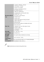
Page 21: ...Quick Reference Guide OFP 21W38 Quick Reference Guide 21 ...

Page 22: ...ick Reference Guide Step7 Fasten the Panel mount screw 12 against the wall so that the entire module can be secured by the Panel mount screws and Panel mount kit brackets 9 Panel mount Screw 12 7 Wall 1 Item Part Name Quantity ...

Page 23: ... Reference Guide OFP 21W38 Quick Reference Guide 23 The diagram is demonstrated by OFT 10W01 but the concept the entire module can be secured by fastening the Panel mount screws against the wall is the same ...

Page 24: ...OFP 21W38 24 OFP 21W38 Quick Reference Guide Step8 Paste the 2 pcs U Plates on the Front Bracket to complete installation 10 U Plate 2 5 Front Bracket 1 Item Part Name Quantity ...

Page 25: ...Quick Reference Guide OFP 21W38 Quick Reference Guide 25 Step9 Paste the Decoration Plate on the U Plate to complete installation 11 Decoration Plate 1 10 U Plate 2 Item Part Name Quantity ...

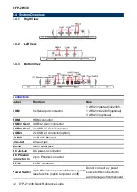
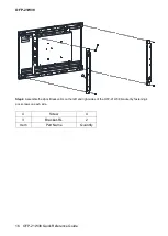
Page 26: ...OFP 21W38 26 OFP 21W38 Quick Reference Guide ...

Page 27: ...de 27 1 7 Wall Mounting Wall mount is the solution for mounting OFP into the wall Size of the opening Installation surface Opening dimension Opening dimension Opening dimension A A Wall box installation dimension Wall box installation dimension Unit mm ...

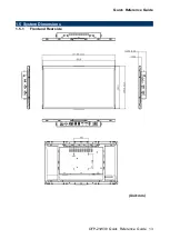
Page 28: ...OFP 21W38 28 OFP 21W38 Quick Reference Guide Screw hole location A A Unit mm ...

Page 29: ...OFP 21W38 Quick Reference Guide 29 Step1 Install the 21 Wall Box and fix it on the wall and use suitable screws to lock the wall box the screws can be purchased according to actual needs 1 Wall box 1 Item Part Name Quantity ...

Page 30: ... 21W38 Quick Reference Guide Step2 Assemble the 2pcs Bracket RL on the left and right sides of the OFP 21W38 bracket by fastening 4 pcs screws on each side 4 Screw 4 3 Bracket RL 2 2 OFP 21W38 1 Item Part Name Quantity ...

Page 31: ...Quick Reference Guide OFP 21W38 Quick Reference Guide 31 Step3 Fasten 10 pcs Hexagon Studs on each side of the OFP 21W38 Bracket 5 Hexagon Stud 10 2 BCX11_156_ASSY 1 Item Part Name Quantity ...

Page 32: ...s screws Step4 4 Insert the Support Bracket H into the locked rectangular hole of the Wall mount kit and insert the unlocked rectangular hole of the Wall mount kit into the Support Bracket V Support Bracket M and fasten 2 pcs Screws on the Front bracket 3 times in this step Step4 5 Insert the rectangular hole of the Wall mount kit into the Support Bracket H and fasten 2pcs screws to the Front brac...

Page 33: ...Quick Reference Guide OFP 21W38 Quick Reference Guide 33 ...

Page 34: ...OFP 21W38 34 OFP 21W38 Quick Reference Guide ...

Page 35: ...ide OFP 21W38 Quick Reference Guide 35 Step5 Fasten the Ground wire with 2 screws on the ground screw holes of Front bracket and Wall box 11 Ground wire 1 4 Screw 2 6 Front bracket 1 1 Wall box 1 Item Part Name Quantity ...

Page 36: ... Quick Reference Guide Step6 Wrap the Kensington lock option around the hole in the Front bracket and attach the lock to the keyhole in the Wall box 12 Kensington lock 1 6 Front bracket 1 1 Wall box 1 Item Part Name Quantity ...

Page 37: ...37 Step6 1 Store the Ground wire and Kensington lock in the Wall box and embed the OFP 21W38 semi finished product into the wall Wall Box Step6 2 Paste the Decoration Plate on the Front bracket to complete installation 10 PC bezel 1 Item Part Name Quantity ...

Page 38: ...OFP 21W38 38 OFP 21W38 Quick Reference Guide ...

Page 39: ...de OFP 21W38 Quick Reference Guide 39 2 Hardware Configuration For advanced information please refer to 1 EMX TGLP included in this manual Note If you need more information please visit our website http www avalue com tw ...

Page 40: ...rt connector COM In RS 232 Mode Signal PIN PIN Signal NDCD 1 6 NDSR NRXD 2 7 NRTS NTXD 3 8 NCTS NDTR 4 9 NRI GND 5 In RS 422 Mode Signal PIN PIN Signal TxD1 1 6 NC TxD1 2 7 NC RxD1 3 8 NC RxD1 4 9 NC GND 5 In RS 485 Mode Signal PIN PIN Signal DATA1 1 6 NC DATA1 2 7 NC NC 3 8 NC NC 4 9 NC GND 5 ...

Page 41: ...Quick Reference Guide OFP 21W38 Quick Reference Guide 41 2 1 2 DC power in connector DC Phoenix connector in Signal PIN V12 24_DCIN 1 GND 2 ...

Page 42: ...OFP 21W38 42 OFP 21W38 Quick Reference Guide 2 2 EMX TGLP Product Overview ...

Page 43: ... disk drives a keyboard or floppy drives In addition the board has a number of jumpers that allow you to configure your system to suit your application If you have any doubts about the best hardware configuration for your application contact your local distributor or sales representative before you make any changes The following tables list the function of each of the board s jumpers and connector...

Page 44: ...ector 10 x 2 wafer pitch 1 25mm USB1 2 USB connector 1 2 JUSB3 4 USB connector 3 4 5 x 2 header pitch 2 54mm LAN1 2 3 4 RJ 45 Ethernet 1 2 3 4 BT1 Battery connector 2 x 1 wafer pitch 1 25mm M2KE1 M 2 2230 Type E Slot M2KB1 M 2 3042 2242 2260 2280 Type B Slot DP1 2 3 4 DP connector 1 2 3 4 JRS485_1 2 Serial Port 1 2 RS485 422 Mode connector 3 x 2 header pitch 2 00mm JLPC LPC connector 5 x 2 header ...

Page 45: ...FP 21W38 Quick Reference Guide 45 2 4 EMX TGLP Setting Jumpers Connectors 2 4 1 Serial port 1 2 pin9 signal select JRI1 JRI2 Default Ring 5V 12V 2 4 2 LVDS Back Light power selection JSBKL1 Default PWM Mode DC Mode JRI2 JRI1 ...

Page 46: ...OFP 21W38 46 OFP 21W38 Quick Reference Guide 2 4 3 AT ATX Power Mode Select JSATX1 Default ATX AT 2 4 4 M2KB1 Voltage setting JP1 Default 3 8V 3 3V ...

Page 47: ...Quick Reference Guide OFP 21W38 Quick Reference Guide 47 2 4 5 Clear CMOS JBAT1 Default Protect Clear CMOS 2 4 6 LCD Inverter connector JBKL1 PIN Signal 1 12V 2 GND 3 LVDS_BKLT_EN 4 LVDS_BKLTCTL 5 5V ...

Page 48: ... NC 6 5 NC GND 8 7 GND LVDS_DATA0_P 10 9 LVDS_DATA1_P LVDS_DATA0_N 12 11 LVDS_DATA1_N GND 14 13 GND LVDS_DATA2_P 16 15 LVDS_DATA3_P LVDS_DATA2_N 18 17 LVDS_DATA3_N GND 20 19 GND LVDS_DATA4_P 22 21 LVDS_DATA5_P LVDS_DATA4_N 24 23 LVDS_DATA5_N GND 26 25 GND LVDS_DATA6_P 28 27 LVDS_DATA7_P LVDS_DATA6_N 30 29 LVDS_DATA7_N GND 32 31 GND LVDS_CLK1_P 34 33 LVDS_CLK2_P LVDS_ CLK1_N 36 35 LVDS_ CLK2_N GND ...

Page 49: ...DP_PANEL_TXN1 9 10 GND EDP_PANEL_TXP1 11 12 EDP_PANEL_AUXN GND 13 14 EDP_PANEL_AUXP EDP_PANEL_TXN2 15 16 GND EDP_PANEL_TXP2 17 18 EDP_PANEL_HPD V35_EDP 19 20 V35_EDP 2 4 10 General purpose I O connector DIO1 Signal PIN PIN Signal DI0 1 2 DO0 DI1 3 4 DO1 DI2 5 6 DO2 DI3 7 8 DO3 DI4 9 10 DO4 DI5 11 12 DO5 DI6 13 14 DO6 DI7 15 16 DO7 SMB_SCL_S0_3P3EXT 17 18 SMB_SDA_S0_3P3EXT GND 19 20 5V Max current ...

Page 50: ...PIN Signal COM_DCD _1 1 2 COM_RXD_1 COM_TXD_1 3 4 COM_DTR _1 GND 5 6 COM_DSR _1 COM_RTS _1 7 8 COM_CTS _1 COM_RI _1 9 10 NC 2 4 12 Serial port2 connector JCOM2 Signal PIN PIN Signal COM_DCD _2 1 2 COM_RXD_2 COM_TXD_2 3 4 COM_DTR _2 GND 5 6 COM_DSR _2 COM_RTS _2 7 8 COM_CTS _2 COM_RI _2 9 10 NC ...

Page 51: ..._5 28 27 COM_RTS _5 COM_DSR _5 26 25 GND COM_DTR _5 24 23 COM_TXD_5 COM_RXD_5 22 21 COM_DCD _5 NC 20 19 COM_RI _4 COM_CTS _4 18 17 COM_RTS _4 COM_DSR _4 16 15 GND COM_DTR _4 14 13 COM_TXD_4 COM_RXD_4 12 11 COM_DCD _4 NC 10 9 COM_RI _3 COM_CTS _3 8 7 COM_RTS _3 COM_DSR _3 6 5 GND COM_DTR _3 4 3 COM_TXD_3 COM_RXD_3 2 1 COM_DCD _3 2 4 14 Serial Port 1 2 RS485 422 Mode connector JRS485_1 2 Signal PIN ...

Page 52: ...OFP 21W38 52 OFP 21W38 Quick Reference Guide 2 4 15 SATA Power connector 1 SPWR1 PIN Signal 1 V5S_SATA 2 GND 3 GND 4 V12S_SATA 2 4 16 Power connector PWR1 Signal PIN PIN Signal GND 2 4 VIN GND 1 3 VIN ...

Page 53: ... USB connector 3 JUSB3 Signal PIN PIN Signal V5A_USB56 1 2 V5A_USB56 USB_DN5 3 4 USB_DN6 USB_DP5 5 6 USB_DP6 GND 7 8 GND 10 GND 2 4 18 USB connector 4 JUSB4 Signal PIN PIN Signal V5A_USB78 1 2 V5A_USB78 USB_DN7 3 4 USB2_ DN8 USB_DP7 5 6 USB2_ DP8 GND 7 8 GND 10 GND ...

Page 54: ...nce Guide 2 4 19 Speaker connector SPK1 Signal PIN SPK_L 1 SPK_L 2 SPK_R 3 SPK_R 4 2 4 20 SPI connector JSPI1 Signal PIN PIN Signal V3 3A_1 8A_SPI 1 2 GND SPI0_CS0 3 4 SPI0_BIOS_CLK SPI0_BIOS_MISO 5 6 SPI0_BIOS_MOSI BIOS_HOLD 7 8 BIOS_WP ...

Page 55: ...Guide 55 2 4 21 Battery connector BT1 PIN Signal 1 RTCBAT 2 GND 2 4 22 Audio connector JFAUD1 Signal PIN PIN Signal LINEOUT_R 1 2 LINEOUT_L GND_AUD 3 4 GND_AUD LINEIN_R 5 6 LINEIN_L MICIN_R 7 8 MICIN_L LINEOUT1_JD 9 10 LINE1 JD MIC1_JD 11 12 GND_AUD ...

Page 56: ...al PIN PIN Signal V3 3A_EC 1 2 GND EC_FSCE 3 4 EC_FSCK EC_FMISO 5 6 EC_FMOSI EC_HOLD 7 8 NC EC_SMCLK_DEBUG 9 10 EC_SMDAT_DEBUG 2 4 24 Miscellaneous setting connector 1 JFPT1 Signal PIN PIN Signal 9 NC PWR_BNT 8 7 Reset PWR_BNT 6 5 Reset PWR_LED 4 3 HD_LED PWR_LED 2 1 HD_LED ...

Page 57: ...us setting connector 2 FPT2 Signal PIN PIN Signal 9 NC GND 8 7 Speaker BLK_DN 6 5 NC BLK_UP 4 3 NC BLK_VR 10K 2 1 Speaker 2 4 26 LPC connector JLPC1 Signal PIN PIN Signal LPC_AD0 1 2 3 3V LPC_AD1 3 4 PLT_BUF_RST LPC_AD2 5 6 LPC_LFRAME LPC_AD3 7 8 CLK_24M_80 LPC_SERIRQ 9 10 GND ...

Page 58: ...OFP 21W38 58 OFP 21W38 Quick Reference Guide 2 4 27 CPU fan connector CPU_FAN1 Signal PIN GND 1 12V 2 CPU_FANIN 3 FAN_PWM0 4 ...

Page 59: ...Quick Reference Guide OFP 21W38 Quick Reference Guide 59 3 BIOS Setup ...

Page 60: ...ntrol over to the operating system While the BIOS is in control the Setup program can be activated in one of two ways By pressing Del or F2 immediately after switching the system on or By pressing the Del or F2 key when the following message appears briefly at the left top of the screen during the POST Power On Self Test Press Del or F2 to enter SETUP If the message disappears before you respond a...

Page 61: ...p program using the keyboard Button Description Move Enter Select Value Esc Exit F1 General Help F2 Previous Values F3 Optimized Defaults F4 Save Exit Setup K Scroll help area upwards M Scroll help area downwards Navigating Through The Menu Bar Use the left and right arrow keys to choose the menu you want to be in Note Some of the navigation keys differ from one screen to another To Display a Sub ...

Page 62: ...uter no longer is able to boot the AMI BIOS supports an override to the NVRAM settings which resets your system to its defaults The best advice is to only alter settings which you thoroughly understand To this end we strongly recommend that you avoid making any changes to the chipset defaults These defaults have been carefully chosen by both BIOS Vendor and your systems manufacturer to provide the...

Page 63: ...will appear on the screen The Main Menu allows you to select from several setup functions and exit choices Use the arrow keys to select among the items and press Enter to accept and enter the sub menu 3 6 1 Main Menu This section allows you to record some basic hardware configurations in your computer and set the system clock ...

Page 64: ... system time option to set the system time Manually enter the hours minutes and seconds Note The BIOS setup screens shown in this chapter are for reference purposes only and may not exactly match what you see on your screen Visit the Avalue website www avalue com tw to download the latest product and BIOS information 3 6 2 Advanced Menu This section allows you to configure your CPU and other syste...

Page 65: ...ated Default Auto Detection This option configures Connectivity Auto Detection means that if Discrete solution is discovered it will be enabled by default Otherwise Integrated solution CNVi will be enabled Disable Integrated disables Integrated Solution NOTE When CNVi is present the GPIO pins that are used for radio 3 6 2 2 CPU Configuration ...

Page 66: ... Technology Disabled Enabled Default When enabled a VMM can utilize the additional hardware capabilities provided by Vanderpool Technology Active Processor Cores All Default 1 2 3 Number of cores to enable in each processor package 3 6 2 3 Power Performance 3 6 2 3 1 CPU Power Management Control ...

Page 67: ...Intel R Speed Shift Technology support Enabling will expose the CPPC v2 interface to allow for hardware controlled P states C states Disabled Enabled Default Enable Disable CPU Power Management Allows CPU to go to C states when it s not 100 utilized Enhanced C states Disabled Enabled Default Enable Disable C1E When enabled CPU will switch to minimum speed when all cores enter C State 3 6 2 4 PCH F...

Page 68: ...ed Enable Disable Me FW Image Re Flash function 3 6 2 5 Trusted Computing Item Options Description Security Device Support Disabled Enabled Default Enables or Disables BIOS support for security device O S will not show Security Device TCG EFI protocol and INT1A interface will not be available 3 6 2 6 ACPI Settings ...

Page 69: ...n the SUSPEDN button is pressed 3 6 2 7 IT8528 Super IO Configuration You can use this item to set up or change the IT8528 Super IO configuration for serial ports Please refer to 3 6 2 7 1 3 6 2 7 5 for more information Item Description Serial Port 1 Configuration Set Parameters of Serial Port 1 COMA Serial Port 2 Configuration Set Parameters of Serial Port 2 COMB Serial Port 3 Configuration Set P...

Page 70: ... 1Serial Port 1 Configuration Item Option Description Serial Port Disabled Enabled Default Enable or Disable Serial Port COM UART 232 422 485 UART 232 Default UART 422 UART 485 Change the Serial Port as RS232 422 485 3 6 2 7 2 Serial Port 2 Configuration ...

Page 71: ...led Default Enable or Disable Serial Port COM UART 232 422 485 UART 232 Default UART 422 UART 485 Change the Serial Port as RS232 422 485 3 6 2 7 3 Serial Port 3 Configuration Item Option Description Serial Port Enabled Default Disabled Enable or Disable Serial Port COM 3 6 2 7 4 Serial Port 4 Configuration ...

Page 72: ... Option Description Serial Port Enabled Default Disabled Enable or Disable Serial Port COM 3 6 2 7 5 Serial Port 5 Configuration Item Option Description Serial Port Enabled Default Disabled Enable or Disable Serial Port COM 3 6 2 8 EC 8528 H W monitor ...

Page 73: ...xed Time Dynamic Time Enable or disable System wake on alarm event Select FixedTime system will wake on the hr min sec specified Select DynamicTime System will wake on the current time Increase minutes s 3 6 2 10 Serial Port Console Redirection Item Options Description Console Redirection Disabled Default Enabled Console Redirection Enable or Disable ...

Page 74: ...ettings Item Options Description Redirection COM Port COM0 Select a COM port to display redirection of Legacy OS and Legacy OPROM Messages 3 6 2 11 USB Configuration The USB Configuration menu helps read USB information and configures USB settings Item Options Description USB transfer time out 1 sec 5 sec 10 sec The time out value for Control Bulk and Interrupt transfers ...

Page 75: ...troller Auto uses default value for a Root port it is 100ms for a Hub port the delay is taken form Hub descriptor Mass Storage Devices Auto Default Floppy Forced FDD Hard Disk CD ROM Mass storage device emulation type AUTO enumerates devices according to their media format Optical drives are emulated as CDROM drives with no media will be emulated according to a drive type 3 6 2 12 Network Stack Co...

Page 76: ...OFP 21W38 76 OFP 21W38 Quick Reference Guide 3 6 2 13 NVMe Configuration 3 6 3 Chipset ...

Page 77: ...Quick Reference Guide OFP 21W38 Quick Reference Guide 77 3 6 3 1 System Agent SA Configuration Item Option Description VT d Disabled Enabled Default VT d capability 3 6 3 1 1Memory Configuration ...

Page 78: ... Option Description Primary Display Auto Default IGFX Select which of IGFX PEG PCI Graphics device should be Primary Display Or select HG for Hybrid Gfx 3 6 3 1 3 VMD Configuration Item Option Description Enable VMD controller Disabled Default Enabled Enable Disable to VMD controller ...

Page 79: ...eference Guide OFP 21W38 Quick Reference Guide 79 3 6 3 2 PCH IO Configuration Item Option Description PCH LAN Controller Enabled Default Disabled Enable Disable onboard NIC 3 6 3 2 1 PCI Express Configuration ...

Page 80: ... I225 Disabled Enabled Default Control the PCI Express Root Port ASPM Disabled Default L0s L1 L0sL1 Auto Set the ASPM Level Force L0s Force all links to L0s State AUTO BIOS auto configure DISABLE Disables ASPM L1 Substates Disabled L1 1 L1 1 L1 2 Default PCI Express L1 Substates settings PCIe Speed Auto Default Gen1 Gen2 Gen3 Select PCIe speed ...

Page 81: ...6 M 2 KeyE Disabled Enabled Default Control the PCI Express Root Port ASPM Disabled Default L0s L1 L0sL1 Auto Set the ASPM Level Force L0s Force all links to L0s State AUTO BIOS auto configure DISABLE Disables ASPM L1 Substates Disabled L1 1 L1 1 L1 2 Default PCI Express L1 Substates settings PCIe Speed Auto Default Gen1 Gen2 Gen3 Select PCIe speed ...

Page 82: ...KeyB Disabled Enabled Default Control the PCI Express Root Port ASPM Disabled Default L0s L1 L0sL1 Auto Set the ASPM Level Force L0s Force all links to L0s State AUTO BIOS auto configure DISABLE Disables ASPM L1 Substates Disabled L1 1 L1 1 L1 2 Default PCI Express L1 Substates settings PCIe Speed Auto Default Gen1 Gen2 Gen3 Select PCIe speed ...

Page 83: ...le SATA Port 0 DevSlp For DevSlp to work both hard drive and SATA port need to support DevSlp function otherwise an unexpected behaviour might happen Please check board design before enabling it Port 1 Disabled Enabled Default Enable or Disable SATA Port SATA Port 1 DevSlp Disabled Enabled Default Enable Disable SATA Port 1 DevSlp For DevSlp to work both hard drive and SATA port need to support De...

Page 84: ...abled Default Control Detection of the HD Audio device Disable HDA will be unconditionally disabled Enabled HDA will be unconditionally enabled 3 6 3 3 Board Panel Configuration Item Option Description Active Panel Disabled Enabled Default Active Internal LVDS eDP Ch7511 to LVDS Enabled Load vbt with EDP 7511 Disabled load ...

Page 85: ...rol Method 1 BIOS 2 OS Driver Panel Brightness 00 25 50 75 100 Default Select Panel back light PWM duty Panel Back Light PWM Frequency 200 Default 300 400 500 700 1k 2k 3k 5k 10k 20k Select Panel back light PWM Frequency ErP Function Disabled Default Enabled ErP Function Deep S5 PWR On After PWR Fail Off Default On Last State AC Ioss resume Wake Up by Ring Disabled Enabled Default Wake Up by Ring ...

Page 86: ...FP 21W38 86 OFP 21W38 Quick Reference Guide 6W SHOW DMI INFO Disabled Default Enabled SHOW DMI INFO 3 6 4 Security Administrator Password Set setup Administrator Password User Password Set User Password ...

Page 87: ...feature is Active if Secure Boot is Enabled Platform Key PK is enrolled and the System is in User mode The mode change requires platform reset Secure Boot Mode Standard Default Custom Secure Boot mode options Standard or Custom In Custom mode Secure Boot Policy variables can be configured by a physically present user without full authentication 3 6 5 Boot ...

Page 88: ...o wait for setup activation key 65535 0xFFFF means indefinite waiting Bootup NumLock State On Default Off Select the Keyboard NumLock state Quiet Boot Disabled Default Enabled Enables or disables Quiet Boot option Boot Option 1 Set the system boot order Boot Option 2 Set the system boot order 3 6 6 Save and exit ...

Page 89: ...ng the changes 3 6 6 2 Discard Changes and Reset Reset system setup without saving any changes 3 6 6 3 Restore Defaults Restore Load Default values for all the setup options 3 6 6 4 Launch EFI Shell from filesystem device Attempts to Launch EFI Shell application Shell efi from one of the available filesystem devices ...

Page 90: ... 21W38 90 OFP 21W38 Quick Reference Guide 4 Drivers Installation Note Installation procedures and screen shots in this section are for your reference and may not be exactly the same as shown on your screen ...

Page 91: ...value Official Website http www avalue com tw Note The installation procedures and screen shots in this section are based on Windows 10 operation system If the warning message appears while the installation process click Continue to go on Step 3 Click Install Step1 Click Next Step 4 Complete setup Step 2 Click Accept ...

Page 92: ...www avalue com tw Note The installation procedures and screen shots in this section are based on Windows 10 operation system If the warning message appears while the installation process click Continue to go on Step 3 Click Start Step 1 Click Begin installation Step 4 Click Reboot now Step 2 Click Next to accept license agreement ...

Page 93: ...bsite http www avalue com tw Note The installation procedures and screen shots in this section are based on Windows 10 operation system If the warning message appears while the installation process click Continue to go on Step 3 Click Next Step 1 Click Next to continue setup Step 4 Click Finish to complete setup Step 2 Click Next ...

Page 94: ...an be found on the Avalue Official Website http www avalue com tw Note The installation procedures and screen shots in this section are based on Windows 10 operation system If the warning message appears while the installation process click Continue to go on Step1 Click Next to Install Step 2 Click Finish to complete setup ...

Page 95: ...te http www avalue com tw Note The installation procedures and screen shots in this section are based on Windows 10 operation system If the warning message appears while the installation process click Continue to go on Step 3 Click Next Step 1 Click Next to continue installation Step 4 Click Yes Step 2 Click Next Step 5 Click Install ...

Page 96: ...OFP 21W38 96 OFP 21W38 Quick Reference Guide Step 6 Click Finish to complete setup ...

Page 97: ...und on the Avalue Official Website http www avalue com tw Note The installation procedures and screen shots in this section are based on Windows 10 operation system If the warning message appears while the installation process click Continue to go on Step 1 Click Next to continue installation Step 2 Click Next ...

Page 98: ...on Windows 10 operation system If the warning message appears while the installation process click Continue to go on Step 3 change path to C and execute the file Step 1 Copy file AscendingSortNetworkAdapterByMac zip to C Step 4 it will generate Avalue folder Step 2 Unzip file AscendingSortNetworkAdapterByMac zip Step 5 Click and enter C Avalue EMX TGLP folder execute administratoramode ExecuteAsce...

Page 99: ...AscendingSortNetworkAdaptersX64 bat it will auto Restart Step 7 Ethernet1 INTEL I219LM Ethernet2 INTEL I225IT Ethernet3 INTEL I210 Ethernet4 INTEL I210 Note If customer would like to patch LAN order sequence please refer to Avalue website for EMX TGLP Sort Network Adapter By Mac Address ...

Page 100: ...e for OFP 21W38 Datasheet LCD Datasheet eDP Touch Screen Datasheet Adapter Datasheet CE FCC test Report Product Design Verification Report Here you can find information for Software development How to flash Android image file Note If you need more information please visit our website http www avalue com tw ...

Reviews: