background image

EARTH DRILL

OPERATORS MANUAL

Document No: 99-95 518001 - Rev 1

Doc Date: 12-12-2013

Part No: 51-8901/ 51-8902

www.avanttecno.com

99-95200403 - ISSUE 8

ENGLISH

Summary of Contents for HD35

Page 1: ...EARTH DRILL OPERATORS MANUAL Document No 99 95 518001 Rev 1 Doc Date 12 12 2013 Part No 51 8901 51 8902 www avanttecno com 99 95200403 ISSUE 8 ENGLISH ...

Page 2: ...Safety Devices 11 Check The Equipment 11 Hazard Classification Only applicable to ANSI Safet Labels 11 Safety Precautions 12 IDENTIFICATION 13 Typical Setup 13 MOUNTING HITCH FITTING 14 HYDRAULIC CONNECTIONS 16 Connecting the Multiconnector System 16 Conventional Quick Couplings 17 Releasing Residual Hydraulic Pressure 17 Hoses Specifications 17 RUNNING IN 18 FITTING THE AUGER 19 PREPARATION 20 WO...

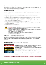
Page 3: ...nsportation Within The Job Site 26 MAINTENANCE LUBRICATION 27 Service Intervals 28 Recommended Oil Change Intervals 29 Recommended Lubricants 29 Oil Change Procedure 30 Component Wear 31 Auger Tooth Replacement 32 Shock Lock Teeth 32 Stump Planer Blade Removal 33 Sharpening Blades 33 Blade Life 33 Pilot Replacement 33 TROUBLESHOOTING 34 WARRANTY STATEMENT 36 ...

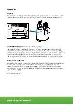
Page 4: ...o products that are intended to be placed on or put into service in the market for the first time The manufacturer or the authorised representative must draw up a Declaration of Conformity Declaration Of Conformity Where Earth Drill Units are supplied in conjunction with Auger Torque Europe Ltd manufactured mounting frames and Augers to form an Earth Drill Assembly Auger Torque Europe Ltd have con...

Page 5: ...X England 44 0 1451 861652 44 0 1451 861660 Declares that the product described Manufacturer Auger Torque Europe Ltd Model Serial Number Conforms to the Machinery Directive 2006 42 EC It also complies with the essential health and safety requirements national standards and the transposed harmonised standards appropriate for this product Signed by Dated The responsible person ...

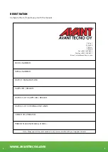
Page 6: ...MANUFACTURE SUPPLIER DEALER DATE SOLD TO SUPPLIER DEALER DATE SOLD TO ORIGINAL END USER OWNER OR OPERATOR PARENT MACHINE MAKE MODEL Ylötie 1 FI 33470 Ylöjärvi Finland Tel 358 3 347 8800 Telefax 358 3 348 5511 E mail sales avanttecno com Note Always quote the serial number in any communication with your supplier dealer ...

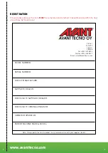
Page 7: ...ser MODEL NUMBER SERIAL NUMBER DATE OF MANUFACTURE SUPPLIER DEALER DATE SOLD TO SUPPLIER DEALER DATE SOLD TO ORIGINAL END USER OWNER OR OPERATOR PARENT MACHINE MAKE MODEL Note Always quote the serial number in any communication with your supplier dealer Ylötie 1 FI 33470 Ylöjärvi Finland Tel 358 3 347 8800 Telefax 358 3 348 5511 E mail sales avanttecno com ...

Page 8: ...www avanttecno com 8 8 For warranty purposes the form on the reverse of this page should be completed and returned to Avant Tecno Oy Ylötie 1 FI 33470 Ylöjärvi Finland ...

Page 9: ...rocedure see page 18 NOTE This operating manual should be used in conjunction with the parent machine s operating instructions Instruction books should be regarded as part of the machine They should always be kept safe with the machine for easy and quick reference New or extra copies can be obtained from your Avant Tecno Oy dealer or direct from Avant Tecno Oy Avant Tecno Oy Earth Drill Units have...

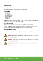
Page 10: ...Know Your Equipment Get to know all you how to operate all controls on the machine and the attachments IF THERE IS SOMETHING IN THE MANUAL WHICH YOU DO NOT UNDERSTAND CONTACT THE MACHINE AGENT OR MANUFACTURER AND ASK THEM TO EXPLAIN IT TO YOU Danger Warning And Caution This symbol below has 3 important meanings when used with the following captions DANGER An IMMINENTLY HAZARDOUS situation that WIL...

Page 11: ...re can penetrate the skin or eyes and cause serious PERSONAL INJURY BLINDNESS OR DEATH Fluid leaks under pressure may not be visible Use a piece of wood or thick cardboard to find leaks DO NOT USE YOUR BARE HANDS Wear safety goggles for eye protection If any fluid is injected into the skin it MUST be surgically removed SEE A DOCTOR IMMEDIATELY Make sure all hydraulic lines are correctly installed ...

Page 12: ...ng operations Check for potential hazards eg Electricity or communication cables etc ALWAYS ensure that the parent machine is secure and stable with it s engine switched off before carrying out any maintenance work ALWAYS ensure the hydraulic oil supply to the attachment is disconnected by uncoupling the hydraulic hose connectors before fitting removing or adjusting the equipment ALWAYS wear head ...

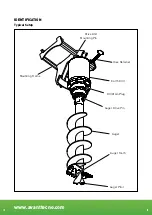
Page 13: ...www avanttecno com 13 13 IDENTIFICATION Typical Setup Drive Unit Mounting Pin Earth Drill Fill Drain Plug Auger Drive Pin Auger Auger Tooth Auger Pilot Mounting Frame Hose Retainer ...

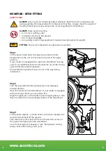
Page 14: ...sition If your loader is equipped with a hydraulic attachment locking system see additional instructions about the use of the locking system from the relevant manuals Ensure that the hydraulic hoses are not in the way during installation Step 2 Turn the quick attach plate hydraulically to an obliquely forward position Drive the loader onto the attachment If your loader is equipped with a telescopi...

Page 15: ...achment or the boom has been lifted at a height of over one metre Excess tilting increases the risk of toppling over We recommend that you lower the attachment onto the ground and secure the locking manually Step 4 Swing the frame to the vertical postion Working as a pair lift the Earth Drill in to place with the port opening facing to the left Align hood ears with the hole in the linkage block Se...

Page 16: ... that the drilling rotation of the Earth Drill Unit is clockwise It is critical that the supply of oil is within the stated flow pressure limits for the particular Earth Drill Refer to the serial plate on the top of the Earth Drill hood see page 4 Connecting the Multiconnector System Align the pins of the attachment connector with corresponding holes of the loader connector The multiconnector will...

Page 17: ...oader Note that the protective caps on the loader and the attachment can be fastened to each other during operation to reduce the accumulation of dirt When disconnecting the standard quick couplings a small amount of oil may drip from the couplings Wear protective gloves and have some cloth at hand to keep the equipment clean Make sure that all three couplings are properly connected otherwise the ...

Page 18: ...orking position For the duration of the running in procedure ensure that no bystanders including animals can get within 6 metres 20 foot of the work area Operate the motor at 30 of rated pressure for 20 minutes in each direction before application of full operating load To further ensure best motor life and maintain warranty refer to page 27 for lubrication instructions 1 2 20 20 ...

Page 19: ...ircuit locked out and its engine switched OFF CHECK that the Auger is the correct model and type to fit the Earth Drill Unit ENSURE that the Auger connections are clean before fitting USE suitably rated lifting equipment if required see data plate for weight Position the Auger in the vertical work position and support it so that it cannot fall over Position the Earth Drill over the Auger and align...

Page 20: ...OTE the type of soil and its condition to enable selection of suitable teeth and pilot ALWAYS carry out a site survey and risk assessment BEFORE starting work AVOID underground hazards such as water gas electricity communication lines etc If in doubt detection equipment and professional advice should always be considered before carrying out any work ...

Page 21: ...d the more down force required Maintain drilling speed DO NOT CONTINUALLY STALL the Earth Drill unit with excessive down force as this will overheat the hydraulic oil and could damage the machine KEEP THE AUGER VERTICAL Fig B Adjust the angle of the arm mounting frame and the position of the parent machine as necessary MAXIMISE efficiency and avoid damaging the Auger assembly by keeping the Auger ...

Page 22: ...sion The timber must be of minimum dimensions 150mm 6 deep x 50mm 2 wide and long enough to span the hole being drilled plus an additional 300mm 12 length at each end Fitting A Fixed Extension When the hole has been drilled to the point where the top of the auger comes within 200mm 8 above ground level Stop drilling Remove the auger from the hole and clear the spoil from the auger Lower the auger ...

Page 23: ...tension are supported by the timber Make sure that the load is spread equally on either side of the hole Remove the Linch Pin and Auger Drive Pin Lift the Earth Drill until the Extension is clear of the Auger and slew it to one side clear of the hole and set it to a height that will allow safe removal of the extension Support the weight of the Extension Remove the Linch Pin and Extension Drive Pin...

Page 24: ...raulic circuit locked out and its engine switched OFF CHECK that the Planer is the correct model and type to fit the Earth Drill Unit ENSURE that the Planer connections are clean before fitting USE suitably rated lifting equipment if required see data plate for weight Position the Planer in the vertical work position and support it so that it cannot fall over Position the Earth Drill over the Plan...

Page 25: ...e blades to engage with a clean horizontal cut If the blades fail to engage move the planer forwards and backwards until blades engage then return tool to upright position Cutting Sequence When removing large stumps the planer can be repositioned to overlap each hole in the sequence shown repeat until the entire stump is removed 6º ...

Page 26: ...nsporting the parent machine on public highways ALWAYS store the Auger and Earth Drill securely and safely when removed from the parent machine taking special care of the hydraulic hoses and connections Transportation Within The Job Site ALWAYS operate the parent machine slowly when on site taking great care to avoid the Auger swinging RECOMMENDED where fitted use the hitch cradle to support the E...

Page 27: ...fire electrical sparks or heat sources All lubricants are toxic and potentially carcinogenic cancer causing Avoid contact with skin and eyes Wear suitable protective clothing and gloves Always use a suitable barrier cream in case of skin contact Always wear eye protection In the event of skin contact wash with soap and water In the event of eye contact wash with water and seek medical advice Do no...

Page 28: ...Weekly Earth Drill pivot pin Oil Lubrication Your Earth Drill has been prefilled with Gear Oil This oil requires regular changing changing the oil at regular intervals will prolong the life of you unit Please refer to the chart on page 29 for recommended oil change intervals Important To maintain product warranty your Avant Tecno Oy Dealer MUST record proof of this first oil change Please note the...

Page 29: ...e frequency Oil change frequency Whichever time period occurs first Recommended Lubricants All units are supplied with 320 AGMA 6EP viscosity oil unless otherwise requested When using or storing the units below 15 C a 150 AGMA 4EP viscosity oil must be used When using or storing units above 35 C a 460 AGMA 7EP viscosity oil must be used Model Oil Quantity ml US pints Grade Type HD35 400 0 85 EP 32...

Page 30: ... oil by running the unit for 15 minutes Fig A Ensure that the unit is safely supported in a horizontal position with the fill drain plugs Fig B 1 2 at top and bottom of the housing 2 Remove drain fill plugs using suitable tooling and allow oil to drain for a minimum of 10 minutes For best results leave to drain overnight 3 Refit drain plug Fig C 2 and fill with oil Refer to page 29 for correct oil...

Page 31: ...f wear NOTE Excessively worn teeth pilots may cause damage to the Auger NOTE Pilots can be replaced by unbolting the old pilot and bolting the new one in it s place For tooth replacement refer to page 32 Earth Tooth NEW OK REPLACE Pilot Bit NEW OK REPLACE S4 70mm 2 3 4 S5 S6 110mm 4 21 64 PA 115mm 4 17 32 Tungsten Tipped Teeth Pilots REPLACE OK NEW ...

Page 32: ...n the tooth Press the tooth and rubber into the tooth holder ensuring that the cut out for the pin is on the correct side You may need to use a soft faced hammer to drive it in fully Insert a new retaining pin into the top of the tooth holder plain end first Drive the pin in ensuring that it locates in the cut out in the tooth Use a pin punch to make sure that the knurled end of the pin is fully e...

Page 33: ... fitted with a Green Silicone Carbide make several small passes against the cutting face ensuring that the cutting edge angle is maintained at 50 degree Blade Life After repeated sharpening the blade will come to the end of its useful life The diagram details acceptable levels of wear Pilot Replacement Remove pilot using a 46mm spanner NOTE Heat may be required to release thread use gloves as pilo...

Page 34: ...rect new parts Seek advice from parent machine dealer Seek advice from Avant Tecno Oy dealer Only use genuine spare parts FAULT Earth Drill Unit will not fit mounting frame Excessive movement in locating pins AUGER DRIVE UNIT ASSEMBLY POSSIBLE CAUSE Incorrect incompatible or non genuine mounting frame Earth Drill Unit Damaged parts Incorrect or worn pins ACTION Obtain fit correct and compatible ge...

Page 35: ... Earth Drill auger size parent machine combination ACTION Test reset or replace to parent machine s specification Seek advice from Avant Tecno Oy dealer Remove auger from ground before starting machine Check tha parent machine hydraulic system is operating correctly and has sufficient oil of the correct grade Check specification Seek advice from Avant Tecno Oy dealer Ensure auger size is compatibl...

Page 36: ... factory may reimburse the price of components purchased by the customer in special cases that have been agreed in advance The warranty does not cover Normal maintenance work or parts and consumables required for it Damages caused by unusual operating conditions or ways of use negligence structural changes made without the consent of Avant Tecno Oy use of non original parts or lack of maintenance ...

Page 37: ...able in your country or region AUGER TORQUE SHOCK LOCK NDS and the AUGER TORQUE LOGO are trademarks of Auger Torque Europe Ltd 2013 Auger Torque Europe Ltd All Rights Reserved Avant Tecno Oy Ylötie 1 FI 33470 Ylöjärvi Finland Tel 358 3 347 8800 Telefax 358 3 348 5511 E mail sales avanttecno com www avanttecno com ...

Reviews: