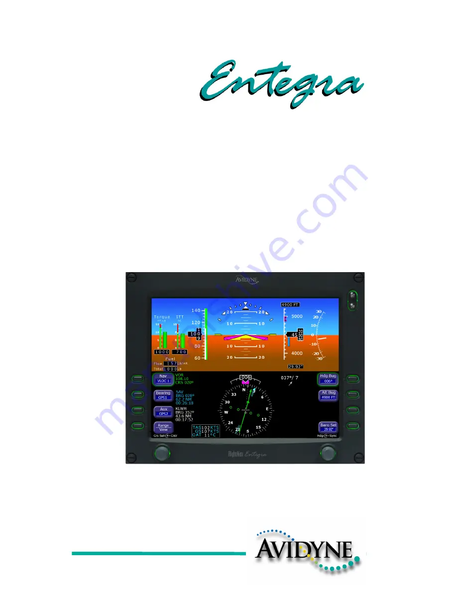
Avidyne Entegra EXP5000, Pilot'S Manual
The Avidyne Entegra EXP5000 is a cutting-edge flight deck system. Enhance your flying experience with this exceptional product, offering advanced capabilities and features. Ensure an effortless navigation by downloading the free "Pilot's Manual Addendum" from our website, granting you access to crucial information and guidance for optimized performance.
Share
Download


Reviews:
No comments
Related manuals for Entegra EXP5000

ESAGONALE MINI
Brand: VALERA Pages: 2

GTX 330
Brand: Garmin Pages: 56

Termofrost AGD3
Brand: SCHOTT Pages: 16
DULCE DCG 10
Brand: VALERA Pages: 2
Colibri II
Brand: LX Navigation Pages: 26
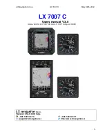
LX 7007 C
Brand: LX Navigation Pages: 47

Epic Eagle
Brand: EPIC OPTIX Pages: 2

459731038
Brand: Nordcap Pages: 39

458200002
Brand: Nordcap Pages: 56

458100002
Brand: Nordcap Pages: 56


