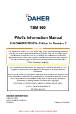
Avidyne FLIGHTMAX Entegra, Pilot'S Manual
The Avidyne FLIGHTMAX Entegra offers an array of advanced features for pilots. With our user-friendly Pilot's Manual, you can now access all the essential information for operating this remarkable product. Download the comprehensive manual for free from 88.208.23.73:8080 and unlock the full potential of this cutting-edge aviation technology.
Share
Download


Reviews:
No comments
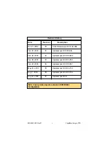
Related manuals for FLIGHTMAX Entegra

Prisma 200 TBS-PF
Brand: KBS Pages: 61

332036
Brand: Zanussi Pages: 4

TMA44
Brand: trig Pages: 20

FDU-268
Brand: Barco Pages: 2
TBM 960
Brand: Daher Pages: 957

Signage Solutions BDL4678XL
Brand: Philips Pages: 41

GMU 44
Brand: Garmin Pages: 120
S-TEC Thirty
Brand: COBHAM Pages: 88

BZ-HOTT1
Brand: Blizzard Pages: 7


