background image

Your journey, Our technology
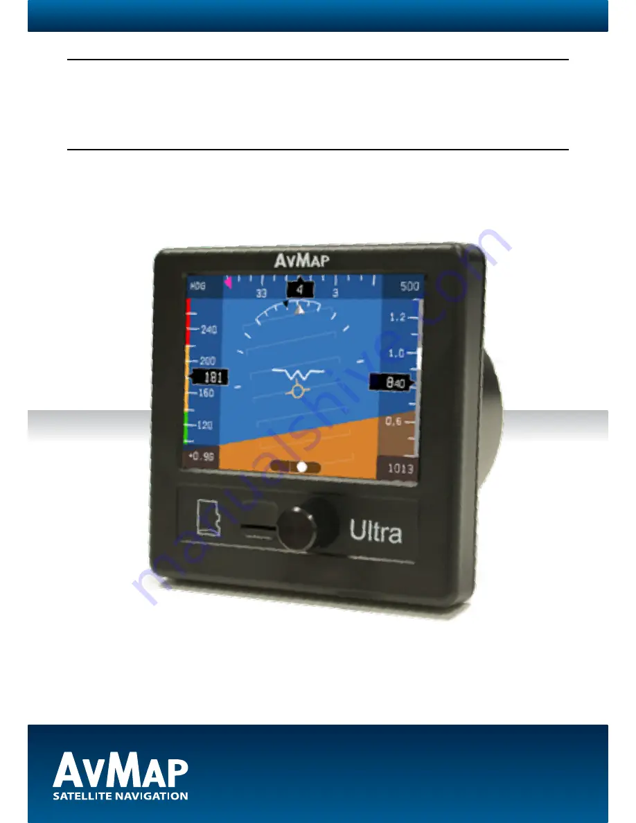
Ultra


EFIS

User and Installation Manual

Product model number: UX0EFS3xAM / UX0EFS5xAM

Software: version 5.21.2R or more recent 

Firmware: version 3.15 or more recent

IMPORTANT: 

Before using this manual check if your Ultra product model number corresponds to the above model number.

Summary of Contents for Ultra EFIS

Page 1: ...stallation Manual Product model number UX0EFS3xAM UX0EFS5xAM Software version 5 21 2R or more recent Firmware version 3 15 or more recent IMPORTANT Before using this manual check if your Ultra product model number corresponds to the above model number ...

Page 2: ......

Page 3: ...ying in safe conditions AvMap disclaims any liability deriving from an improper use of the device in a way that may violate the flight and navigation rules regulations and safety 1 Overview 4 2 Installation 5 2 1 Location 5 2 2 Mechanical installation 5 2 3 Connections wiring 8 3 System Calibration 10 3 1 Horizon alignment calibration AHRS 10 3 2 Compass calibration magnetometer 11 3 3 Altimeter c...

Page 4: ...iver Connecting the external GPS receiver to the Ultra the system provides the pilot with navigation information on the HSI page providing its position direction and radials relative to reference navigation points Preloaded navigation POI s Ultra is preloaded with Jeppesen navigation POI s Airports NDB s and VOR s Coverage available Europe Africa North America South America Asia Australia For upda...

Page 5: ...bration see Chapter 3 IMPORTANT The Ultra contains a magnetometer and other precision electrical sensors The location selected for installation should be clear of strong magnetic or electromagnetic disturbances as much as possible Avoid installing the Ultra near electronic equipment other digital EFIS radios transponders etc AC or variable DC cables alternators electrical motors ferrous materials ...

Page 6: ... 05 The screw length that need to be used for panel installation depend on the panel thickness and is based on the following formula 5mm l t 8mm l length of the screw t thickness of the panel Use the screws and metal washer included in the box for standard panel thickness of up to 3mm For thicker instrument panels use longer screws and use the formula to choose the right screw length ...

Page 7: ...ckness IMPORTANT Make sure you respect the screw length formula to avoid damaging the plastic of the Ultra Use light thread locker to prevent screw loosening with vibration Use the Cutting template included in the box to cut out the panel see Figure 4 Aircraft instrument panel ...

Page 8: ...pported by mean of a T coupler not included in the Ultra box Pitot Tube Airspeed Indicator Altimeter Static Port 2 3 Connections wiring On the back of the unit there are 4 connectors the Pitot port the static port the power supply serial connector and the GPS receiver connector see Figure 5 External Positive Power 10 35Vdc External Power GND RS232 Serial Data TX RS232 Serial Data RX GND signal gro...

Page 9: ...at has a clear view of the sky It can be mounted on the aircraft s dashboard using the included Velcro strip The GPS receiver must have a clear view of the sky in order to receive satellite signals GPS uses line of sight signals to locate and track satellites If the signals are obstructed by dense objects such as aluminum steel or even heavy ice the Ultra will not operate properly Signals may also...

Page 10: ...ed in an instrument panel that is aligned with the aircraft lateral axis but not perpendicular to the straight level flight attitude the simple horizon alignment calibration procedure must be executed Note The horizon calibration corrects also a roll offset if it is not perfectly alligned with the aircraft laterall axis Horizon alignment calibration procedure Execute this calibration procedure to ...

Page 11: ... calibration Wait 2 minutes to let the electronic sensors stabilize before operating the system 3 2 Compass calibration magnetometer The purpose of this procedure is to compensate magnetic disturbances the Ultra is subject to due to aircraft metal structures and electromagnetic components These disturbances if not compensated could alter the heading value provided by the system For this reason the...

Page 12: ... by keeping the rotation knob pressed for 5 seconds and release see chapter 4 for further details Push again the rotor knob select CALIBRATE to enter the calibration menu then select COMPASS and select CALIBRATE Mag clear done message will pop up on the display The Ultra display shows Point to NORTH Press NEXT when ready Make sure that the aircraft nose is pointed to the magnetic north 0 radial on...

Page 13: ...5 minutes before moving the aircraft Note In the SETUP menu you can choose to display compass heading in reference to magnetic north or true north see chapter 4 Note If the calibration fails or the compass indicator is not enabled repeat the calibration procedure If several calibration attempts fails review the installation location of the Ultra Magnetic disturbance could be too high in the area s...

Page 14: ...g the calibration process a GPS fix is required the device must be powered since at least 5 min and the aircraft must not be in movement IMPORTANT Check periodically the altimeter accuracy and recalibrate when you notice an offset By any doubt or continuous altimeter offset readings AvMap recommends to proceed with the altimeter factory calibration 3 3 2 Factory calibration The factory calibration...

Page 15: ...again the rotation knob To go back to the PFD display mode push the rotation knob select PFD and confirm by pushing again the rotation knob To enter the SETUP mode from either the PFD or HSI mode keep the rotation knob pressed for 5 seconds 4 2 PFD mode The PFD shows critical flight information like attitude airspeed altitude as well as other less critical flight variables like turn coordination h...

Page 16: ... be entered in the SETUP menu see paragraph 4 4 Note In the SETUP menu select your preference unit for speeds knots kph mph m s Altitude is shown in number representation as well as on a vertical tape Underneath the tape there is a Kollsmann window where the user can adjust the QNH setting Note In the SETUP menu select your preference unit for altitude feet ft meter m Note Due to fluctuations in p...

Page 17: ... PFD mode the display brightness can ne adjusted by pressing the knob and select BRT In the lower left corner on the display the brightness percentage is shown rotate the knob to change brightness and press to confirm Aircraft specific V speed reference values Set the aircraft specific V speed values to get the right information on the air speed ranges bar Refer to the aircraft operating manual to...

Page 18: ...ted or when the magnetometer has an failure The COG value is always shown in a numeric value on the right side of the HSI page The COG data is based on GPS source Note The COG value is anyway always shown on the right side of the HSI page Note If the compass source is GPS the device shows COG above the compass If the compass source is the magnetometer the device shows HDG above the compass Both ca...

Page 19: ...s the VOR radial POI ID distance in nm km or miles POI name and two frequencies Note The VOR function on the Ultra is a digital version of the traditional VOR instrument The course deviation indicator and TO FROM flag are based on the selected radial its GPS position aircraft heading and the coordinates of the selected VOR destination point from the preloaded POI database VOR navigation settings W...

Page 20: ...erating manual to find the correct values of your aircraft Note In the SETUP menu select your preference unit for speeds knots kph mph m s Navigation POI management Ultra is preloaded with Jeppesen navigation POI s Airports NDB s and VOR s In the DATABASE menu you can choose IMPORT to update navigation POI s on the Ultra through the microSD card Make sure the microSD card is inserted in the Ultra ...

Page 21: ...of each NMEA message Select NMEA OUT in the SETUP menu and select Serial A or Serial B in order to setup the desired settings per serial and confirm by pressing the knob Select ON OFF in order to enable or disable the NMEA OUT function and confirm by pressing the knob Select the required baudrate 4800 9600 144400 19200 38400 and confirm by pressing the knob Select ON OFF for each NMEA message in o...

Page 22: ...e heading correctly using gyroscopic and other internal means Magnetometer failures on start up or during prolonged periods lead to incorrect heading readings What to do Perform magnetometer calibration If the problem persists and the magnetometer is external check connection If problem persists relocate magnetometer in the aircraft according to installation instructions and recalibrate If problem...

Page 23: ...he sensor system on the unit is no longer speaking to the symbol generator CPU What to do This problem can occur because the unit is configured wrong because the software on the device inside it has been erased or because of an internal failure The first two causes can be solved by updating the software with the latest available software version If a software update doesn t resolve the failure the...

Page 24: ...yros accelerometers and magnetometers Acceleration range 3 axis 8 g Rotation range 1600 deg s Air data sensors range 10 to 215 kts 1000 to 40000 ft UAV Navigation Motion processor Micro SD slot 1 5 m 59 free wires power supply cable 10 35 VDC 2 serial ports RS 232 Consumption 12 V DC 100 mA nominal Included accessories GPS receiver U Blox NEO 6Q with 1 5 m 59 cable Mounting KIT cutting template 4x...

Page 25: ...n time fix quality number of satellites used height of antenna HDOP Horizontal Dilution of Precision differential reference information and age GSA GPS receiver operating mode satellites used in the navigation solution reported by the GGA sentence GSV Number of satellites in view satellite numbers elevation azimuth and SNR value RMB Data status Cross Track Error direction to steer origin destinati...

Page 26: ...www avmap it www avmap us www avmap com br ÑMAEFSAM1AE040ËÓ MAEFSAM1AE040 Ultra EFIS ...

Reviews: