background image

Pillar Drills


User Manual


Code 505203

Code 505204
Code 505205
Code 505206

505203 
AT2001DP

505204 
AT2501DP

505205 
AT2801FDP

505206 
AT3202FDP

Summary of Contents for Trade AT2001DP

Page 1: ...Pillar Drills User Manual Code 505203 Code 505204 Code 505205 Code 505206 505203 AT2001DP 505204 AT2501DP 505205 AT2801FDP 505206 AT3202FDP ...

Page 2: ... Specification 07 Assembly 08 09 10 11 12 13 Illustration and Parts Description 14 15 Changing the Speed 16 Speed Select Table 17 Removing the Chuck Assembly 18 Maintenance 19 Troubleshooting 20 Parts Breakdown List 21 22 22 23 24 25 26 27 28 29 Wiring Diagram 30 31 Copied from CE Certificate The undersigned Galen Chen authorised by Qingdao D D Electromechanical Technologies Co Ltd Jiaozhou Branch...

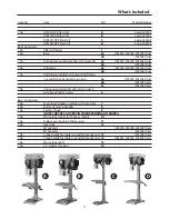
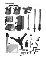
Page 3: ... rise and fall rack and retaining ring 5a 505203 505204 Only 5b 505205 Only 5c 505206 Only 1 No Chuck guard assembly with micro switch and three Phillips screws 6 Bags Containing 1 No Lever feed handle assembly with Hex bolt 7 2 No Bristol clamping handles 8 1 No Keyless Chuck 9 NOTE CHUCKS CAN VERY IN SIZE DEPENDING ON MODEL 1 No Morse taper arbor for chuck assembly 10 1 No Pulley cover knob Phil...

Page 4: ...What s Included 4 2 3 1 a a a a b b b c b 4 6 7 8 9 10 11 12 13 15 16 14 5 ...

Page 5: ...are damaged If any damage is visible have the machine inspected repaired by a suitably qualified person If it is necessary to replace the plug it is preferable to use an unbreakable type that will resist damage Only use a 13 Amp plug make sure the cable clamp is tightened securely Fuse at 13 Amp If extension leads are to be used carry out the same safety checks on them and ensure that they are cor...

Page 6: ...ls are the correct type and size are undamaged and are kept clean and sharp this will maintain their operating performance and lessen the loading on the machine Above all OBSERVE make sure you know what is happening around you and USE YOUR COMMON SENSE General Safety Instructions for Drilling Machines 1 Do not operate the machine without carrying out a preliminary inspection 2 Check that the speed...

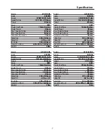
Page 7: ...55 x 355mm Table Tilt 45 to 45 Base Size 480 x 280mm Overall L x W x H 720 x 370 x 1 100mm Weight 66kg Model AT2801FDP Code 505205 Power 550W 230V 1ph Speed Range 16 160 3 000rpm Throat 215mm Taper 3MT Chuck Cap Type 16mm Keyless Chuck Travel 80mm Max Chuck to Table 610mm Max Chuck to Base 1 100mm Diameter of Column 80mm Table Size 355 x 355mm Table Tilt 45 to 45 Base Size 480 x 280mm Overall L x ...

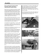
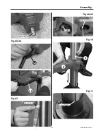
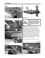
Page 8: ...k into the square recess in the mounting body casting ensure that it is engaged with the pinion see figs 8 9 and lower the combined mechanism over the column 5 Allow it to slide down the column until the rise and fall rack is located in the cup chamfer in the top of the mounting flange see figs 10 11 Replace the cup chamfered retaining collar over the column and slide it down onto the top of the r...

Page 9: ...Assembly 9 Fig 05 06 Fig 07 Fig 08 09 Continues Over Fig 10 Fig 11 Machined flat 14 13 Top of rack Rise and fall rack Pinion Cup chamfer 5 5 ...

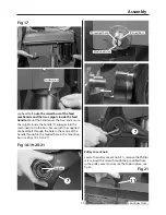
Page 10: ... the column 5 when the head is fitted see fig 16 Put the lower assembly you have just been working on in the designated position make sure it is stable and lift the drillhead 1 over the column 5 and let it drop into place Set the drill head approximately fore and aft and lock in position using the two caphead grub screws mentioned earlier Check that the drillhead is immobile Everything on the dril...

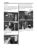
Page 11: ...Secure with the supplied caphead bolt through the hole in the centre of the handle through to the tapped hole in the mounting boss see figs 18 19 20 21 Fig 18 19 20 21 Pulley cover knob Locate the pulley cover knob 11 remove the Phillips screw insert the screw through the pre drilled hole in the pulley cover and secure the knob in place see fig 22 Fig 21 Continues Over Grub screw Spigots Raised bo...

Page 12: ...2 23 Fig 22 23 Plug the power connector into the micro switch unit unitl it clips home see fig 24 Fig 24 6 Thread holes Phillips screw Power connector Morse taper arbor chuck Radial Drills Only Locate the morse taper arbor 10 insert the arbor into the keyless chuck 9 then slot the assembly up into the quill Using a high faced mallet lightly tap it home see figs 25 26 Fig 25 26 10 9 Bolt the pillar...

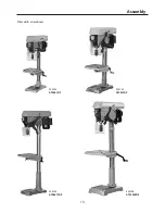
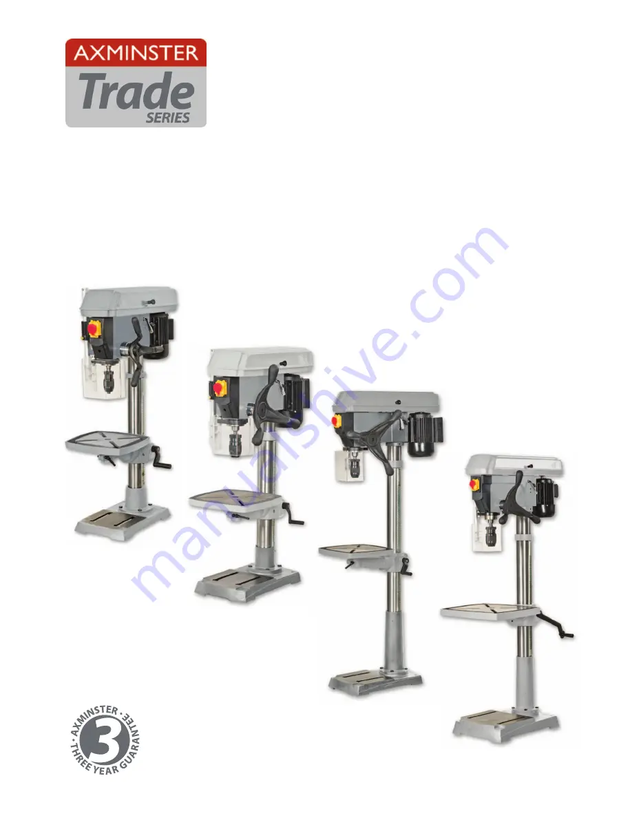
Page 13: ...Assembly 13 505203 AT2001DP 505204 AT2501DP 505205 AT2801FDP 505206 AT3202FDP Pillar drills assembled ...

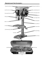
Page 14: ... lever lock Crank handle Rise and fall rack Mounting flange Base casting Retaining collar Lever feed handle Keyless chuck Drill table Chuck guard Chuck guard micro switch On Off switch shroud Drill column Bristol clamping handle Pulley drive belt cover Quill Pulley Motor Pulley Jockey Pulley Drive belt tensioning ...

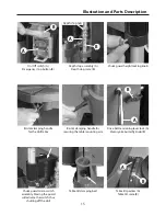
Page 15: ... clamping handle for the drill table Drive belt tensioning lever lock A Motor yoke butterfly knob B Bristol clamping handle for securing the table mounting arm Chuck guard micro switch assembly Moving the guard will activate the switch thus shutting off the drill Table tilt pointer A Table tilt scale B Table tilt clamping bolt B B A A A B B A Depth stop nuts ...

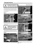
Page 16: ...e fig 28 to check the belts move freely Tension the whole belt train by turning the drive belt tensioning lever B anti clockwise to WARNING TAKE CARE NOT TO TRAP YOUR FINGERS WHEN REPOSITIONING THE BELT ON THE PULLEYS Refer to the speed select table and ascertain the belt positions for the speed you require Move the belts to these positions Fig 28 Fig 29 30 31 32 Turn anti clockwise to tension the...

Page 17: ...Speed Select Table 17 505204 AT2801DP 505203 AT2001DP 505205 AT2801FDP 505206 AT3202FDP ...

Page 18: ...g damaged and lower the quill to its maximum depth by turning the feed lever handle Fig 33 Preparation You wil require the morse taper drift 11 Fig 34 Removing the chuck Morse taper arbor Quill slot Fig 35 While holding the handle in place turn the chuck to line up the morse taper arbor in the quill s machined slot See fig 34 Insert the morse taper drift 11 in the quill s slot thus pushing the mor...

Page 19: ...t coating of machine oil on the quill then to spread the oil If the machine is going to stand idle for any length of time a light coat of spray or machine oil over the column and table will prevent rusting WARNING DISCONNECT THE MACHINE FROM THE MAINS SUPPLY BEFORE CONTINUING WARNING DO NOT USE THE MACHINE IF THE POWER CABLE HAS BECOME DAMAGED WARNING DO NOT ATTEMPED TO REPAIR IT YOURSELF CONTACT ...

Page 20: ...rill bit Wood splinters on underside 1 No back up material under workpiece 1 Use back up material Workpiece torn loose from hand 1 Not supported or clamped properly 1 Support workpiece or clamp it Drill bit binds in workpiece 1 Work piece pinching drill bit or excessive feed pressure 2 Improper belt tension 1 Support Work piece or clamp it 2 Adjust tension Excessive drill bit runout or wobble 1 Be...

Page 21: ...Parts Breakdown List 505203 21 Continues Over ...

Page 22: ...6103007A 1 31 Spindle 16103001 1 32 Ball bearing GB276 89 80204 1 33 Self tapping screw GB845 85 ST4 2x9 5 4 34 Switch KJD12A 1 35 Pan head screw GB818 85 M5x16 3 36 Wire terminal CE 5 1 37 Switch box 16102008D 1 38 Pan head screw GB818 85 M5x6 2 39 Lockwasher GB862 1 87 5 2 40 Special screw set 16102021 1 41 Hex nut GB6172 86 M12 2 42 Spring cap 16104008 1 43 Quill spring 16104009 1 44 Spring cov...

Page 23: ...A33 16105011C 1 80 Knob 16105008 1 81 Belt A 29 16805010C 1 82 Ball bearing GB276 89 60202 2 83 Center pulley 16105006 1 84 Idler pivot 16105007 1 85 Motor pulley 16105005 1 86 Hex Socket head screw GB80 85 M8x12 1 87 Pan head screw GB818 85 M3x25 2 88 Micro switch 16105013 2 1 89 Pan head screw GB818 85 M3x16 2 90 Micro switch XN 5 1 91 Micro switch housing 16105013 1 1 92 Hex nut GB6170 86 M3 4 ...

Page 24: ...Parts Breakdown List 505204 505205 24 ...

Page 25: ...ll bearing GB276 89 80205 1 33 Self tapping screw GB845 85 ST4 2x9 5 4 34 Switch KJD12A 1 35 Pan head screw GB818 85 M5x16 3 36 Wire terminal CE 5 1 37 Switch box 16202008D 1 38 Pan head screw GB818 85 M5x6 2 39 Lock washer GB862 1 87 5 2 40 Special screw set 16102021 1 41 Hex nut GB6172 86 M12 2 42 Spring cap 16104008 1 43 Quill spring 16104009 1 44 Spring cover 16104007A 1 45 Depth stop thread a...

Page 26: ...1A 1 80 Knob 16105008 1 81 Belt A29 16205010A 1 82 Ball bearing GB276 89 60202 2 83 Center pulley 16205006 1 84 Idler pivot 16205007 1 85 Motor pulley 16205005 1 86 Pan head screw GB818 85 M3x25 2 87 Micro switch 16105013 2 1 88 Pan head screw GB818 85 M3x16 2 89 Micro switch XN 5 1 90 Micro switch housing 16105013 1 1 91 Hex Nut GB6170 86 M3 4 92 Cable microswitch 16102029C 1 93 Pan head screw GB...

Page 27: ...Parts Breakdown List 505206 27 Continues Over ...

Page 28: ...C 1 33 Spindle 20103001 1 34 Ball bearing GB276 89 80206 1 35 Thrust bearing GB301 87 8706 1 36 Self tapping screw GB845 85 ST4 2x9 5 4 37 Switch KJD12 1 38 Wire terminal 16102019 1 39 Pan head screw GB818 85 M6x15 2 40 Pan head screw GB818 85 M6x30 2 41 Switch box 20102008D 1 42 Pan head screw GB818 85 M5x6 2 43 Lockwasher GB862 1 87 5 2 44 Special screw set 16102021 1 45 Hex Nut GB6172 86 M12 2 ...

Page 29: ...09 1 82 Pulley nut 20102025 1 83 V belt A33 20105010E 1 84 Knob 16105008D 1 85 Belt A29 16205011A 1 86 Ball bearing GB276 89 60202 2 87 Center pulley 20105006 1 88 Idler pivot 20105007 1 89 Motor pulley 20105005B 1 90 Pan head screw GB818 85 M3x25 2 91 Micro switch cover 16105013 2 1 92 Pan head screw GB818 85 M3x16 2 93 Micro switch XN 5 1 94 Micro switch housing 16105013 1 1 95 Hex Nut GB6170 86...

Page 30: ...Wiring Diagram 505203 505204 505205 30 ...

Page 31: ...Wiring Diagram 505206 31 ...

Page 32: ...CNC machines for industry and education Small machines for the home engineer Compressors and tools for home or workshop use durable and great value FreeThreeYear Guarantee on Axminster Hobby Trade and Industrial Series woodworking and engineering machines Axminster Air compressors and Air Tools and bench top grinders no registration necessary just proof of purchase We will repair or replace at our...

Reviews: