background image

PT-6SBT

PENTIUM II

AT MAINBOARD

USER’S  MANUAL

DOC NUMBER  UM-SBT-E1

.................................................................

PRINTED IN TAIWAN

Summary of Contents for PT-6SBT

Page 1: ...PT 6SBT PENTIUM II AT MAINBOARD USER S MANUAL DOC NUMBER UM SBT E1 PRINTED IN TAIWAN ...

Page 2: ...SiS5600 AT PENTIUM II MAINBOARD USER S MANUAL DOC NUMBER UM SBT O1 PRINTED IN TAIWAN ...

Page 3: ...1 3 1 INSTALLING THE DRAM MODULES 3 1 3 2 CONNECTORS 3 2 3 3 JUMPERS 3 15 4 AWARD BIOS SETUP 4 21 4 1 GETTING STARTED 4 21 4 2 MAIN MENU 4 22 4 3 CONTROL KEYS 4 22 4 4 STANDARD CMOS SETUP 4 23 4 5 BIOS FEATURES SETUP 4 24 4 6 CHIPSET FEATURES SETUP 4 27 4 7 POWER MANAGEMENT SETUP 4 32 4 8 INTEGRATED PERIPHERALS 4 38 4 9 PNP PCI CONFIGURATION 4 41 4 10 LOAD SETUP DEFAULTS 4 44 4 11 SUPERVISOR PASSW...

Page 4: ...ged by any improper action Please refer to the Section 3 3 for details WAKE ON LAN In order to support the Wake On LAN feature the system requires a ATX type SPS switching power supply and it must be able to provide at least 700 mA of driving capability on the 5V standby voltage Please refer to the Section 3 3 for details WARNING The Static Electricity may cause damage to the components on the mai...

Page 5: ...e and decide the frequency for you or you may use the BIOS setup program to select the CPU clock by yourself Two channels PIO and Ultra DMA 33 Bus Master mode PCI IDE ports one Floppy Disk control port two high speed Serial ports UARTs and one multi mode Parallel port and supports PS 2 mouse IR and USB ports are built on the board The Pentium II and Celeron Processor are the 64 bit processors with...

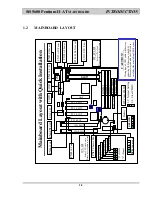
Page 6: ...2 IR Port CN2 PS 2 Mouse CN13 CPU Fan CN1 AT K B JP9 Clear CMOS 1 2 3 1 2 Normal Setting 2 3 Clear CMOS CN14 AT Power CN16 WOL CN17 Chassis Fan CAUTION Wrong type of USB cable will destroy either the USB device or the M B Please always handle the USB cable carefully when installing USB devices DIMM 2 DIMM 1 DIMM 3 CN8 FDC CN9 IDE1 CN10 IDE2 SLOT1 AGP CN15 ATX Power 1 G G S S 1 1 1 RS Reset button ...

Page 7: ... Path 8 bit 16 bit 32 bit 64 bit Address Path 32 bit PC SYSTEM CHIPSET SiS5600 and SiS5595 system chipset SUPER I O CHIPSET FDC37C669 FRONT SIDE BUS FREQUENCY 66 6 75 83 3 95 100 112 124 133MHz Selected by system BIOS MEMORY DRAM Three 168 pin DIMM sockets onboard support 3 3V SDRAM DIMM modules Max memory size 768MB CACHE 256KB or 512KB L2 Cache memory built in Pentium II processor 0KB or 128KB L...

Page 8: ...IR and ASKIR or Fast IR optional compatible IR port HARDWARE MONITORING 1 Monitor the system voltages CPU temperature and two cooling fan speeds 2 Supports LDCM optional ACPI This feature is valid only when ATX power supply is connected Advanced Configuration and Power Interface ACPI function is strongly recommended by PC 98 because it will let you have many additional features and that will make ...

Page 9: ...ayers PCB 220mm x 240mm Baby AT Form Factor ENVIRONMENT LIMIT 1 Operating Temperature 10 to 40 50 to 104 2 Required Airflow 50 linear feet per minute across CPU 3 Storage Temperature 40 to 70 40 to 158 4 Humidity 0 to 90 non condensing 5 Altitude 0 to 10 000 feet ...

Page 10: ...chanism CPU Holder l One CD diskette for device drivers and utility programs This mainboard contains electrostatic sensitive components and it can be easily damaged by static electricity So please leave it sealed in the original packing until when installing A grounded anti static mat is recommended when unpacking and installation Please also attached an anti static wristband to your wrist and hav...

Page 11: ... on the system power you will see the Keyboard LED lights when system power is off it is because the standby 5V is still active When the Password is enabled in the system BIOS you will have to reboot the PC system to activate the setting when you see the POST Power On Self Test is completed the setting is changed and stored in the CMOS memory Having finished the procedure you may turn the power of...

Page 12: ... the serial port the system power will be turned on and start to receive the incoming messages automatically To enable the Modem Ring In feature you have to run the BIOS setup utility and enable the Ring Power Up Control option it is in the POWER MANAGEMENT SETUP please refer to Section 4 7 for the settings Note This function is not available when using the internal MODEM card WAKE ON LAN WOL Ther...

Page 13: ... power button PW switch to turn the system power off You can only use the power switch on the power supply to power off the PC system IMPORTANT In case that you make a wrong BIOS setup and you can not power on the PC system you may press and hold the INSERT key and then press the PW button to turn the system power on When you are using such way to power on you PC system the system BIOS will force ...

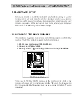
Page 14: ...board integrates a main memory controller that supports a 64 bit DRAM interface The DRAM controller supports the following features 1 DRAM type Synchronous SDRAM DRAM 2 Memory size 8MB to 768MB 3 Memory modules supported Single and double density 3 3V DIMMs ISA SLOT ISA SLOT PCI SLOT K B PCI SLOT PCI SLOT CN3 CN4 DIMM 2 DIMM 1 DIMM 3 CN8 FDC CN9 IDE1 CN10 IDE2 SLOT1 AGP PCI SLOT DRAM Subsystem Dia...

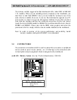
Page 15: ...d then install the faster ones in DIMM2 and DIMM3 Please also run the BIOS setup program and select the parameters which is comply with the slowest module installed on the mainboard Note In order to increase of the system performance and steability install memory modules starting from DIMM 1 is recommended 3 2 CONNECTORS The connectors on mainboard will be used to connect the accessories or periph...

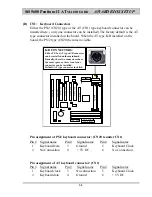
Page 16: ...d on the mainboard Basically these two connectors share the same space so there is only one connector can be installed Default AT type connector installed ISA SLOT ISA SLOT PCI SLOT PCI SLOT PCI SLOT CN3 CN4 CN8 FDC CN9 IDE1 CN10 IDE2 SLOT1 AGP PCI SLOT Pin assignment of PS 2 keyboard connector CN20 is under CN1 Pin Signal name Pin Signal name Pin Signal name 1 Keyboard Data 3 Ground 5 Keyboard Cl...

Page 17: ...tor CN4 COM 2 Serial Port 2 Connector ISA SLOT ISA SLOT PCI SLOT K B PCI SLOT PCI SLOT CN8 FDC CN9 IDE1 CN10 IDE2 SLOT1 AGP PCI SLOT CN 3 CN 4 COM 1 COM 2 Ping assignment of serial port connector 1 6 Pin Signal name Pin Signal name 1 DCD Data Carrier Detect 6 DSR Data Set Ready 2 RD Received Data 7 RTS Request To Send 3 TD Transmit Data 8 CTS Clear To Send 4 DTR Data Terminal Ready 9 RI Ring Indic...

Page 18: ... SLOT PARALLEL PORT CN 5 Pin assignment of parallel port 1 14 Pin Signal name Pin Signal name 1 STROBE 14 AUTO FEED 2 Data Bit 0 15 ERROR 3 Data Bit 1 16 INIT 4 Data Bit 2 17 SLCT IN 5 Data Bit 3 18 Ground 6 Data Bit 4 19 Ground 7 Data Bit 5 20 Ground 8 Data Bit 6 21 Ground 9 Data Bit 7 22 Ground 10 ACK 23 Ground 11 BUSY 24 Ground 12 PE 25 Ground 13 SLCT 26 N C 13 25 ...

Page 19: ...CN10 IDE2 SLOT1 AGP PCI SLOT Pin assignment of USB connector CN 7 CN 6 Pin Assignment Pin Assignment 5 Ground BLACK WIRE 1 5V DC RED WIRE 4 Ground BLACK WIRE 2 DATA WHITE WIRE 3 DATA GREEN WIRE 3 DATA GREEN WIRE 2 DATA WHITE WIRE 4 Ground BLACK WIRE 1 5V DC RED WIRE 5 Ground BLACK WIRE H CN8 Floppy Disk Control Port Connector using IRQ6 DMA 2 CN8 FDC Connector ISA SLOT ISA SLOT PCI SLOT PCI SLOT P...

Page 20: ...E 2 Connectors Secondary IDE Port 170H IRQ 15 CN9 IDE 1 CN10 IDE 2 ISA SLOT ISA SLOT PCI SLOT PCI SLOT PCI SLOT SLOT1 AGP PCI SLOT K CN12 IR FIR Infrared Rays Connector 1 2 3 4 5 5VDC FIR RECEIVE IR RECEIVE GROUND IR TRANSMIT IR FIR INFRARED RAYS CN 12 ISA SLOT ISA SLOT PCI SLOT PCI SLOT PCI SLOT SLOT1 AGP PCI SLOT ...

Page 21: ... Cooling Fan Power Connector CN13 CPU Cooling Fan Ground 12V DC Fan Sense Signal 1 2 3 ISA SLOT ISA SLOT PCI SLOT PCI SLOT PCI SLOT SLOT1 AGP PCI SLOT M CN14 AT Power Connector CN 14 AT Power Connector ISA SLOT ISA SLOT PCI SLOT PCI SLOT PCI SLOT SLOT1 AGP PCI SLOT ...

Page 22: ...5V DC White 10 10 5V DC Red 11 11 5V DC Red 12 12 5V DC Red Note There are two connectors from the switching power supply P8 P9 Wrong connection will cause permanent damage to the mainboard Be sure to make the power connector correctly all the time Joint the black cable and then have the connectors connected to the mainboard N CN15 ATX Power Connector CN15 ATX Power Connector ISA SLOT ISA SLOT PCI...

Page 23: ...und 3 Ground 14 PS ON 4 5V DC 15 Ground 5 Ground 16 Ground 6 5V DC 17 Ground 7 Ground 18 5V DC 8 PW OK 19 5V DC 9 5V SB 20 5V DC 10 12V DC 20 10 O CN16 WOL Wake On LAN Connector CN 16 WOL ISA SLOT ISA SLOT PCI SLOT PCI SLOT PCI SLOT SLOT1 AGP PCI SLOT 1 2 3 Pin assignment of WOL Connector 1 2 3 Pin Signal name Pin Signal name Pin Signal name 1 5V standby 2 Ground 3 WOL Signal ...

Page 24: ...A series of connectors are designed on the board to connect the push buttons and LED indicators Followings are the details RS Reset Button connector HL HDD LED connector TL Turbo LED SL Sleep LED connector PW Power On Off Suspend switch P W S L T L H L R S ISA SLOT ISA SLOT PCI SLOT PCI SLOT PCI SLOT SLOT1 AGP PCI SLOT 1 RS Reset Button Connector Pin Signal name Pin1 2 Function 1 Reset Control Ope...

Page 25: ...al Suspend Switch Connector 5 a When this mainboard has the ATX power supply connected According to the setup in CMOS the PW connector has two functions It can be the Power Switch or Suspend Switch of your PC system please refer to Section 4 7 and section 4 8 for BIOS setup Q If the setup in CMOS is Delay 4 Sec the switch function will be A When system is power off A short click on this switch the...

Page 26: ...wer is on Click on this switch the system will be powered off instantly 5 b When this mainboard has the AT power supply connected the PW switch can only be used as the suspend switch A When the BIOS setup is Delay 4 sec The PW switch can be used as a suspend switch When it is first pressed the PC system will be turned into suspend mode when clicked again the PC system will be back to the normal st...

Page 27: ...ck Connector ISA SLOT ISA SLOT PCI SLOT PCI SLOT PCI SLOT SLOT1 AGP PCI SLOT SPK Speaker connector 1 Pin Signal name 1 5V DC 2 Speaker Data Signal 3 Speaker Data Signal 4 Speaker Data Signal 5 No Connection 5 PWR LED KBLOCK Panel Power LED and Key Lock Connector 1 Pin Signal name 1 Pullup 5V DC for Power LED 2 Ground 3 Ground 4 Keyboard Lock 5 Ground 5 ...

Page 28: ... labeled with optional means they are optional on the mainboard and the related components are normally not populated on the board In order to make the mainboard works properly please make sure all jumper settings are at correct before installing this mainboard A JP1 Keyboard OnNow Function Selection This mainboard supports the OnNow function The OnNow function will allow you to use Keyboard passw...

Page 29: ...T ISA SLOT PCI SLOT PCI SLOT PCI SLOT SLOT1 AGP PCI SLOT JP4 JP3 JP2 JP2 JP3 JP4 BUS CLOCK AGP CLOCK PCI CLOCK 2 3 2 3 2 3 112 MHz 74 7 MHz 37 3 MHz 2 3 2 3 1 2 66 8 MHz 66 8 MHz 33 4 MHz 2 3 1 2 2 3 124 MHz 82 7 MHz 41 3 MHz 2 3 1 2 1 2 75 MHz 75 MHz 37 5 MHz 1 2 2 3 2 3 133 3 MHz 88 7 MHz 44 3 MHz 1 2 2 3 1 2 83 3 MHz 66 6 MHz 33 3 MHz 1 2 1 2 2 3 95 MHz 63 5 MHz 31 75 MHz 1 2 1 2 1 2 100 MHz 66...

Page 30: ...ram before you can use these jumper settings to select the CPU clock ratio Note the setting in the system BIOS has the higher priority than the jumper setting ISA SLOT ISA SLOT PCI SLOT PCI SLOT PCI SLOT AGP PCI SLOT JP7 JP6 JP5 JP8 JP5 2 3 JP6 2 3 1 2 2 3 2 3 2 3 1 2 2 3 2 3 1 2 JP8 1 2 2 3 2 3 1 2 1 2 JP7 2 3 1 2 1 2 1 2 1 2 Clock 233MHz 266MHz 300MHz 333MHz 366MHz 1 2 2 3 400MHz 2 3 2 3 SLOT1 2...

Page 31: ...ds and then return it to the original position pin 1 2 3 Re connect the AC power cable HOW TO MAKE JUMPER SETTING TO SELECT CPU CLOCK Basically there are two parameters which will decide the system speed the Front Side Bus FSB speed it is also called BUS clock and CPU clock ratio When you have installed the processor onto the mainboard the system BIOS will detect the CPU type and decide the FSB sp...

Page 32: ...or 66MHz FSB clodk Pentium II 233 266 300 and 333MHz processors Celeron 266 300 300A 333 and 366MHz processors Processors for 100MHz FSB clodk Pentium II 350 400 450 and 500MHz processors HOW TO DECIDE THE CPU CLOCK RATIO Modify the formula mentioned mentioned above and we will get CPU Frequency FSB Clock Clock Ratio Now we can use the formula above to calculate the CPU clock ratio Please refer to...

Page 33: ...information of your information of CPU frequency and its FSB speed In order to let you have a better picture of the calculation the procedures are summarized as following 1 Check the data sheet for your CPU frequency 2 Check the data sheet and get the FSB clock of your CPU 3 Use the following formula to calculate the CPU clock ratio CPU Frequency FSB Clock Clock Ratio ...

Page 34: ...te a diagnostics and initialization procedure In case that there is any error or malfunction detected the BIOS will give a series of beep sound or display the error message on screen When the system is normal the simulate figure Fig 5 1 will be displayed on the screen when the system is powered on xxxx xxxx Fig 4 1 Initial Power On screen During the power on self testing POST the following message...

Page 35: ...ge Color Time Date Hard Disk Type Fig 4 2 CMOS SETUP MAIN MENU screen 4 3 CONTROL KEYS Listed below is the explanation of the keys displayed at the bottom of the screens which will be used in the CMOS SETUP program Arrow Keys Use the arrow keys to move the cursor to the desired item Enter Select the desired item F1 Display the help screen for the selected feature Shift F2 To change the screen colo...

Page 36: ...to 0 0 0 0 0 0 Auto Secondary Slave None 0 0 0 0 0 0 Drive A 1 44M 3 5 in Drive B None Base Memory 640 K Floppy 3 mode support Disabled Extended Memory xxxxxx K Video EGA VGA Other Memory xxxxxx K Halt On All Errors Total Memory xxxxxx K ESC Quit Select Item PU PD Modify F1 Help Shift F2 Change Color Fig 4 3 STANDARD CMOS SETUP screen MODE The BIOS on the mainboard provides three different modes t...

Page 37: ...oot Up NumLock Status On Boot Up System Speed High Memory Parity Check Enabled Typematic Rate Setting Disabled Typematic Rate Chars Sec 6 Typematic Delay Msec 250 Security Option Setup ESC Quit Select Item PCI VGA Palette Snoop Disabled F1 Help PU PD Modify Assign IRQ For VGA Enabled F5 Old Values Shift F2 Color OS Select For DRAM 64MB Non OS2 F7 Load Setup Defaults Report No FDD For WIN 95 Yes Fi...

Page 38: ...Self Test will skip some test and speed up the boot process If you find the system is working normally you can always enable this feature so that you don t have to wait too long on the POST Boot Sequence default setting A C SCSI This field allows you to use some other device to boot the operating system The options available are A C SCSI C A SCSI C CDROM A CDROM C A D A SCSI E A SCSI F A SCSI SCSI...

Page 39: ...lect Enabled the system board will use the parity bit to check the memory sub system When select Disabled the system board will not check the parity bit Assign IRQ for VGA default setting Enabled Some of the VGA display card has some additional feature on the board and it may need the IRQ signal When the system board need more IRQ signal for other devices and your VGA does not use the IRQ you may ...

Page 40: ...rge Time FP 2T ESC Quit Select Item CAS Pulse Width for FP 2T F1 Help PU PD Modify CPU to PCI Burst Mem WR Enabled F5 Old Values Shift F2 Color SDRAM Input Signals Delay 0 5ns F7 Load Setup Defaults SDRAM Output Signals Lead 0 0ns Fig 4 5 CHIPSET FEATURES SETUP screen This section allows you to configure the system based on the specific features of the installed chipset This chipset manages bus sp...

Page 41: ... default setting 3T The precharge time is the number of cycles it takes for the RAS to accumulate its charge before DRAM refresh If insufficient time is selected refresh may be incomplete and the DRAM may fail to retain data The Choice 2T 3T 4T 5T RAS to CAS Delay default setting 3T When DRAM is refreshed both rows and columns are addressed separately This setup item allows you to determine the ti...

Page 42: ... The choice x 1 1 1 x 2 2 2 SDRAM WR Retire Rate default setting 1WS The field is designed to select the wait state of memory sub system The choice 1WS 0WS RAMW Assertion Timing default setting 3T RAMW is an output signal to enable local memory writes Do not attempt to make change to this field from the default value unless you have the sufficient technical background The choice 2T 3T CAS Precharg...

Page 43: ...e Choices are Enabled Disabled AGP Aperture Size default setting 64MB Select the size of the Accelerated Graphics Port AGP aperture The aperture is a portion of the PCI memory address range dedicated for graphics memory address space Host cycles that hit the aperture range are forwarded to the AGP without any translation See www agpforum org for APG information The choice 4 MB 8MB 16 MB 32 MB 64 M...

Page 44: ...pport delay transactions cycles Select Enabled to support compliance with PCI specification version 2 1 The choice Enabled Disabled Auto Detect DIMM PCI Clk default setting Enabled When enabled the system board will detect the clock speed for DIMM and PCI clock The choice Enabled Disabled Spread Spectrum Default setting Disabled When you select Enabled the special feature designed in the system ch...

Page 45: ...by à off Power Button Over Ride Instant Off Video Off Method Blank Screen Ring Power Up Control Disabled Doze speed div by 2 8 KB Power ON Password Enter Stby speed div by 1 8 Power Up by Alarm Disabled Modem Use IRQ 3 PM Timers HDD Off After Disable Doze Mode Disable Standby Mode Disable Suspend Mode Disabled PM Events ESC Quit Select Item HDD Ports Activity Enabled F1 Help PU PD Modify COM Ports...

Page 46: ...our modes Min Power Saving Minimum power management Doze Mode 1 hr Standby Mode 1 hr Suspend Mode 1 hr and HDD Power Down 15 min Max Power Saving Maximum power management ONLY AVAILABLE FOR SL CPU S Doze Mode 1 min Standby Mode 1 min Suspend Mode 1 min and HDD Power Down 1 min User Defined Allows you to set each mode individually When not disabled each of the ranges are from 1 min to 1 hr except f...

Page 47: ...selection will cause the system to turn off the vertical and horizontal synchronization ports and write blanks to the video buffer Blank Screen This option only writes blanks to the video buffer DPMS Select this option if your monitor supports the Display Power Management Signaling DPMS standard of the Video Electronics Standards to select video power management values Doze Speed div by Default se...

Page 48: ...ns HDD Off After Default setting Disable By default this item is Disabled meaning that no matter the mode the rest of the system the hard drive will remain ready Otherwise you have a range of choices from 1 to 15 minutes or Suspend This means that you can elect to have your hard disk drive be turned off after a selected number of minutes or when the rest of the system goes into a Suspend mode Doze...

Page 49: ...ed default any event occurring at a LPT printer port will awaken a system which has been powered down VGA Activity Default setting Enabled When select Enabled default any event occurring at VGA will awaken a system which has been powered down IRQ 3 7 9 1 NMI Default setting Enabled When select Enabled activity will neither prevent the system from going into a power management mode nor awaken it Th...

Page 50: ...will power off the PC system Please refer to Section 2 for details The choice Instant Off Delay 4 Sec Ring Power Up Control Default setting Disabled When you select Enabled a signal from ring from the external modem will returns the system to Full On state The choice Enabled Disabled Power Up by Alarm Default setting Disabled When you select Enabled there appear some additional selection fields It...

Page 51: ...RPM Secondary Slave UltraDMA Auto IN0 V 11 70 V IN1 V 5 12 V IDE Burst Mode Enabled IN2 V 3 41 V IN3 V 2 05 V IDE HDD Block Mode Enabled Onboard FDC Controller Enabled Onboard UART 1 3F8 IRQ4 Onboard UART 2 2F8 IRQ3 Onboard UART 2 Mode Standard Onboard Parallel Port 378 IRQ7 Parallel Port Mode Normal Fig 5 7 INTEGRATED PERIPHERALS setup screen WARNING The selection fields on this screen are provid...

Page 52: ... Auto Mode 0 Mode 1 Mode 2 Mode 3 Mode 4 IDE Burst Mode Default setting Enabled Selecting Enabled reduces latency between each drive read write cycle but may cause instability in IDE subsystems that cannot support such fast performance If you are getting disk drive errors try setting this value to Disabled This field does not appear when the Internal PCI IDE field above is Disabled The choice Enab...

Page 53: ...fault setting Enabled This mainboard built in a PS 2 mouse port In case that you prefer to connect your mouse to the serial port instead of using the PS 2 mouse you may choose Disable in this field so that the IRQ12 can be released for the other devices If you are using the PS 2 mouse leave this field Enabled USB Controller Default setting Enabled Select Enabled if your system contains a Universal...

Page 54: ... INT B IRQ 4 assigned to PCI ISA PnP Assign IRQ For USB Enabled IRQ 5 assigned to PCI ISA PnP IRQ 7 assigned to Legacy ISA IRQ 9 assigned to PCI ISA PnP IRQ 10 assigned to PCI ISA PnP IRQ 11 assigned to PCI ISA PnP IRQ 12 assigned to PCI ISA PnP IRQ 14 assigned to Legacy ISA IRQ 15 assigned to Legacy ISA DMA 0 assigned to PCI ISA PnP DMA 1 assigned to PCI ISA PnP ESC Quit Select Item DMA 3 assigne...

Page 55: ... PnP DMA0 1 3 5 6 7 assigned to When resources are controlled manually assign each system DMA channel as one of the following types depending on the type of device using the interrupt Legacy ISA Devices compliant with the original PC AT bus specification requiring a specific interrupt such as IRQ4 for serial port 1 PCI ISA PnP Devices compliant with the Plug and Play standard whether designed for ...

Page 56: ... setting refers to the hard disk drive itself rather than individual partitions Since each IDE controller supports two separate hard drives you can select the INT for each Again you will note that the primary has a lower interrupt than the secondary as described in Slot x Using INT above Selecting PCI Auto allows the system to automatically determine how your IDE disk system is configured ...

Page 57: ...may use this option to load the SETUP default values from the BIOS default table It is easy to load the default value simply highlight the LOAD SETUP DEFAULTS field and then press the Enter key when you see the LOAD SETUP DEFAULTS Y N displayed on the screen response to it with Y and then press the Enter key the SETUP default values will be loaded Basically the SETUP default settings are the best ...

Page 58: ...Exit Setup Shift F2 Change Color Time Date Hard Disk Type The password entry in this field will be used to check the authority when power on Whenever there is the password stored in this fields the correct password will be requested so that the PC system will continue to load the operation system You can enter up to eight alphanumeric characters here When you have typed in the password and pressed...

Page 59: ...he mainboard by giving a set of hard disk parameters Sometimes it is not easy for users to find the proper parameters for their IDE hard disk drive In order to help users to find the parameters the system BIOS provides a convent way the auto detection of IDE hard disk drive To run the auto detection program is extremely easy Move the selection bar to IDE HDD AUTO DETECTION and then press Enter the...

Page 60: ...NG INTEGRATED PERIPHERALS PNP PCI CONFIGURATION LOAD SETUP DEFAULTS ESC Quit Select Item F10 Save Exit Setup Shift F2 Change Color Time Date Hard Disk Type This option will save all setup value to CMOS memory and then exit the SETUP routine Move the selection bar to SAVE EXIT SETUP and then press the Enter key Confirm with the Y and Enter keys to the screen prompt and the setup information will be...

Page 61: ...AULTS ESC Quit Select Item F10 Save Exit Setup Shift F2 Change Color Time Date Hard Disk Type This item exit the setup routine without saving any changed values to CMOS RAM When you do not want to save your change to the CMOS memory you may choose to run this option and the setting what you made in the BIOS setup routine will be given away Move the selection bar to EXIT WITHOUT SAVING and click on...

Reviews: