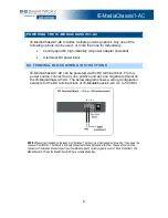
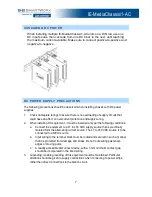
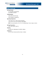
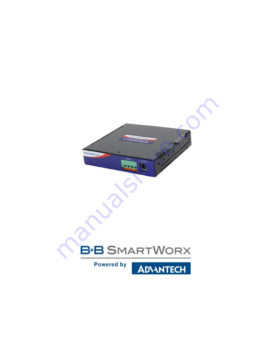
background image


IE-MediaChassis/1-AC 

USER MANUAL


Summary of Contents for IE-MediaChassis/1-AC

Page 1: ...IE MediaChassis 1 AC USER MANUAL ...

Page 2: ...mericas 707 Dayton Road Ottawa IL 61350 USA Phone 1 815 433 5100 Fax 1 815 433 5105 Advantech B B SmartWorx Europe Westlink Commercial Park Oranmore Co Galway Ireland Phone 353 91 792444 Fax 353 91 792445 www advantech bb com support advantech bb com ...

Page 3: ...tallation 4 DIN Rail Mounting 5 Powering the IE MediaChassis 1 AC 6 DC Terminal Block Wiring Instructions 6 Cascading DC Power 7 DC Power Supply Precautions 7 Specifications 8 B B SmartWorx Technical Support 9 Statements Guidelines Precautions 9 FCC Radio Frequency Interference Statement 9 Fiber Optic Cleaning Guidelines 10 Electrostatic Discharge Precautions 11 Standards Compliances 12 ...

Page 4: ...by tightening the captive screw NOTE Please refer to the online installation guide for the module for configuration and operation information NOTE The power source in this chassis is not isolate and cannot support positive reference ground systems typically used in Telco environments The MediaChassis 2 DC and the iMediachassis 6 DC are suitable alternates INSTALLING T H E IE MEDIACHASSIS 1 AC IE M...

Page 5: ... from B B SmartWorx The DIN rail clips include screws to allow installation on a DIN rail Install the screws into DIN rail clips which should be mounted perpendicular to the DIN rail Snap the converter onto the clips To remove the converter from the DIN rail insert a flat head screwdriver into the slot to gently pry the converter from the DIN rail Wallmount Bracket DIN rail Mounting ...

Page 6: ... one positive and any one negative terminal on the IE MediaChassis 1 AC The below diagram shows a wiring configuration example for the DC terminal block of IE MediaChassis 1 AC 7 to 50 VDC NOTE When using stranded wire the leads must be tinned The chassis is protected against mis wiring if mis wired the chassis will not function The chassis is internally connected to the negative power terminal Th...

Page 7: ...installing DC equipment it must be installed only per the following conditions a Connect the equipment to a 7 to 50 VDC supply source that is electrically isolated form the alternating current source The 7 to 50 VDC source is to be connected to a SELV source b Input wiring to the terminal block must be routed and secured in such a manner that it is protected from damage and stress Do not route wir...

Page 8: ...maximum Operating Temperature 25 to 85 C 13 to 185 F with DC terminal 10 to 50 C 14 to 122 F with AC wall adapter NOTE The stated temperature 25 to 85 C is for IE MediaChassis it does not apply to module s Storage Temperature 45 to 85 C 49 to 185 F Humidity 5 to 95 non condensing 0 to 10000 ft altitude Dimensions 2 3h x 10 9w x 10 2d cm 0 91h x 4 30w x 4 00d in ...

Page 9: ...ay cause harmful interference to radio communications Operation of this equipment in a residential area is likely to cause harmful interference in which the user will be required to correct the interference at his own expense Any changes or modifications not expressly approved by the manufacturer could void the user s authority to operate the equipment The use of non shielded I O cables may not gu...

Page 10: ...rd to diagnose problems in an installation 2 Dust caps are installed at the factory to ensure factory clean optical devices These protective caps should not be removed until the moment of connecting the fiber cable to the device Should it be necessary to disconnect the fiber device reinstall the protective dust caps 3 Store spare caps in a dust free environment such as a sealed plastic bag or box ...

Page 11: ...rap is not available maintain grounded contact with the system unit throughout any procedure requiring ESD protection 3 Hold the units by the edges do not touch the electronic components or gold connectors 4 After removal always place the boards on a grounded static free surface ESD pad or in a proper ESD bag Do not slide the modules or standalone units over any surface WARNING Integrated circuits...

Page 12: ...d of separately from regular household waste It is the consumer s responsibility to dispose of this and all equipment so marked through designated collection facilities appointed by government or local authorities Following these steps through proper disposal and recycling will help prevent potential negative consequences to the environment and human health For more detailed information about prop...

Reviews: