background image

I N S - P A F B 1 C _ E N   I n s t r u c t i o n   G u i d e :   F r o n t   B u m p e r    


P a g e  

1 | 12


Thank you for choosing a B-PWR product, designed by passionate riders who focus on what users really need. 


1. SAFETY INSTRUCTIONS  

To avoid any unfortunate situations, we recommend that you get to know how your modified vehicle handles before using it in extreme 

conditions. 


Read all the instructions carefully before installing this product. 


If you do not have the tools or technical knowledge needed to ensure proper installation, have the product installed by an authorized 

dealer. 


It is essential that you follow the installation procedures, possess general mechanical knowledge and use appropriate tools to 

ensure a safe and reliable installation.  


Improper use or installation of the product, or any modifications made to adapt the product for use in a context other than that for 

which it was intended, voids the warranty and may result in SERIOUS INJURIES. 


B-PWR and all its affiliated companies, as well as its suppliers and distributors, are not responsible for any consequences 

whatsoever resulting from an incorrect installation or an improper use of the product. 


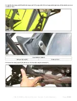
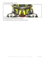
This guide provides detailed instructions for installing the product. 


PAFB-1C 


Polaris snowmobile Axys platform 


For safety reasons, this kit needs to be installed by a person with general mechanical knowledge using the proper tools. 


The illustrations in this document indicate the typical structure of the various assemblies. It is therefore possible that they do not 

represent the exact form of the parts or the manufacturing details. These illustrations are intended to identify parts that perform an 

identical or similar function. 


Summary of Contents for PAFB-1C

Page 1: ...per use or installation of the product or any modifications made to adapt the product for use in a context other than that for which it was intended voids the warranty and may result in SERIOUS INJURI...

Page 2: ...30 Torx Socket T3 Drill Bit 1 4 T7 Hand Riveter Not Shown T4 Ratchet T8 6 mm Allen Key 3 PARTS ITEM DESCRIPTION PART NUMBER QTY P1 Front Bumper Part 1 FB3A BL 1 P2 Front Bumper Part 2 FB3B BL 1 P3 M6...

Page 3: ...product Make sure you have enough space to work properly Make sure to have the required tools Note Unless differences occur between left hand LH and right hand RH sides the procedures are shown for on...

Page 4: ...A F B 1 C _ E N I n s t r u c t i o n G u i d e F r o n t B u m p e r P a g e 4 12 4 2 Disconnect connectors attached to center panel 4 3 Disengage two 2 locking clip of center panel 4 4 Remove cente...

Page 5: ...u i d e F r o n t B u m p e r P a g e 5 12 4 5 Remove screw nut and keep ground in a visible position for reinstallation 4 6 Remove two 2 screws securing bumper using T27 Torx socket T6 4 7 Remove scr...

Page 6: ...u i d e F r o n t B u m p e r P a g e 6 12 4 8 Remove and keep exhaust retaining spring 4 9 Remove screw nut and keep exhaust retaining spring plate 1 Exhaust retainingspringplate 4 10 Drill two 2 riv...

Page 7: ...I N S P A F B 1 C _ E N I n s t r u c t i o n G u i d e F r o n t B u m p e r P a g e 7 12 4 11 Remove bumper 4 12 Drill two 2 rivets with drill bit 1 4 T3 as shown...

Page 8: ...P a g e 8 12 5 INSTRUCTIONS 5 1 Install front bumper part 1 P1 in position on vehicle 5 2 Locate front bumper part 1 P1 with a M6 X 25 mm hexagonal flanged screw P3 M6 nylon lock nut P5 and exhaust re...

Page 9: ...part 1 P1 with a M6 X 25 mm hexagonal flanged screw P3 M6 nylon lock nut P5 and ground as shown Hand tighten only 1 GroundlocatedonLHside 5 4 Secure front bumper part 1 P1 with two 2 M6 X 25 rounded...

Page 10: ...5 Tighten to specification two 2 M6 nylon lock nut P5 with two 2 10 mm wrench key T2 as shown TIGHTENING TORQUE M6 Nylon Lock Nut P5 10 N m 2 N m 5 6 Secure front bumper part 1 P1 with two 2 3 16 riv...

Page 11: ...11 12 5 8 Install front bumper part 2 P2 with front bumper part 1 P1 using a M6 X 25 mm hexagonal flanged screw P3 and a M6 nylon lock nut P5 as shown TIGHTENING TORQUE M6 nylon lock nut P5 10 N m 2...

Page 12: ...u i d e F r o n t B u m p e r P a g e 12 12 5 10 Here is final result of installation of assembly 5 11 Install various panels in reverse sequence of removal procedure Note Ensure that previously remov...

Reviews: