background image

Battery Installation

Replace the battery at the start of each
irrigation season and when the low battery 
symbol              appears.

Use a 9V alkaline top quality battery only.

1.  Using a Phillips screw driver, remove the
     four battery cover screws.
2. Remove the battery cover and seal.
3. Replace the battery.
4. After reattaching the seal, put the cover
    back, and secure with the four screws.
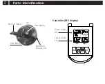
G75 - DFC 

Differential Filtration 

Controller

425

717

010

1 (6/20

)

• English

10

Maintenance

 screws

 Battery cover

 seal

When replacing the seal, push seal tabs

into slots.

11

12

Troubleshooting

No water

Battery dead

Off Mode

Valve # select

is incorrect

Shut Off

Sleep

Battery dead

Open water

Replace battery

Set Auto Mode

#Correct valve select

Press any button

Press MODE

Replace battery

No FC

occurance

Valve does

not work

Blank

 display

 Problem       Cause              Solution

Guarantee

Baccara  products are guaranteed to be free from
defects in material and workmanship for a period 
of one year from the date of delivery.
This guarantee does nor apply where equipment is 
not used and  installed strictly in accordance with 
Baccara specifications and Users Guide. Neither 
does it apply to failures caused by lightning strikes 
or damage due to freezing temperatures or mecha-
nical causes (e.g. lawn mowers). Baccara is not 

To receive guarantee benefits, customers should 
return defective units along with the receipt to the 

 nearest Baccara distributor.

Baccara reserves the right to alter, modify or 
redesign its products, pricing and guarantee at all 
times without creating any liability for the 
obsolescence of customer inventory of such parts 
or products.


This manufacturer guarantee policy may apply
differently in different countries.

liable for indirect, incidental or  consequential 

damage in connection with the use of equipment.
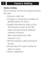
13

Flo

w Chart f

or G75 -DF

C Differ

ential Filtr

ation Contr

oller

Users Guide

Mode 1 sec

Mode

Mode

Aut

o Mode

No displa

y

>2sec

Set v

alv

es

on time

Sec

Min

Mode

Int

erv

al time

betw

een

FC

if Min = A

select

Mode

Valv

es select

deselect

PROGRAMMING

3 v

alv

es

Min

H

rs

®

Summary of Contents for G75-DFC

Page 1: ...G75 DFC Differential Filtration Controller 4257170101 6 20 English Users Guide ...

Page 2: ...and sensor interface The DFC controller is offered as DC Latch only and it is suitable for Baccara solenoid Latch 4 ohm The controllers operates up to three solenoids The Controller shows the actual DIF pressure and the pressure SET point The Flushing Cycle FC begins when DIF SET appears Display The LCD display shows Actual DIF pressure SET point pressure FC counter Faucet icon displayed whilst FC...

Page 3: ...sure 14bar 200psi Electrical Power supply DC unit 9V battery Internal memory retains settings when power supply disconnected Mounting DP 2 52mm diameter 2 ft 60 cm 3 wires cable High and low pressure ports 1 8 BSP NPT male High pressure port marked on housing Important Connect High pressure before Low pressure Disconnect Low pressure before High pressure ...

Page 4: ...Parts Identification 2 Electric cable Pipe fitting Mounting screws x 2 Pipe fitting Controller DFC display Upper digits UD Lower digits LD DP ...

Page 5: ...Wires connections DC White Black Yellow Blue Green G75 DFC Black Black Red Orange Black Red Orange Black Diff Sensor 3 ...

Page 6: ... types wrap stranded wire around solid wires See 1A 2 Insert wires through flexible sealing fingers and bend wires wires into either V Channel 3 Push inner sleeve into pre filled outer sleeve until double locked Pre filled silicone fuller waterproofs the connection Do not reuse connector LV9000 Wire connectors Installation instructions ...

Page 7: ...twist Place stripped wires with ends even lead stranded wires slightly 4 Twist connector onto wires pushing firmly until hand tight DO NOT over torque 5 Swipe excess sealant in and around conductors DO NOT REUSE Operating Modes Auto Off FC counter rest Manual FC UD Upper Digits LD Lower Digits ...

Page 8: ...ss SET then back to Auto Manual FC 1 From Auto Mode press SET and together FC starts Display shows Hand and Faucet icons VALVE and operating valve blink 2 When FC is completed the MODE returns to Auto 3 To stop Manual FC press SET and together FC will stop and return to Auto This interval value will be the max time between two consecutive FC if DIF pressure does not execute FC Range 23 hrs 59 min ...

Page 9: ... Off This mode is for OFF season or to stop Auto Mode permanently LD shows OFF No pressure measuring process occurs Display will shut off as in Auto Mode ...

Page 10: ...tent 2 For RESET press MODE and together UD shows c000 then back to Auto 3 If RESET is not needed press SET then back to Auto Manual FC 1 From Auto Mode press SET and together FC starts Display shows Hand and Faucet icons VALVE and operating valve blink 2 When FC is completed the MODE returns to Auto 3 To stop Manual FC press SET and together FC will stop and return to Auto ...

Page 11: ...adings of DIF SET before FC starts Sample Interval time Auto as the DIF becomes closer to the SET point the interval time between samples shortens Max Interval 60 secs Min Interval 5 sec Off time between valves during FC 20 sec Consecutive FC count number for alarm 5 count Sensor calibration Factory Setting 7 ...

Page 12: ...me default 40 sec range 5 min 59 sec Same time for all valves 1 To set Valve on Time press MODE until below display appears 2 Use and to adjust seconds 3 Press SET to continue 4 Use and to adjust minutes 5 Press SET to complete setting ...

Page 13: ...es not execute FC Range 23 hrs 59 min A If A is selected this setting is ignored 1 To set Interval Time between FC press MODE one long press then one short press The below display appears Default A Interval time between FC Programmable Setting Select Valve no 2 Use and to adjust minutes If A is selected press SET to complete this setting 3 Press SET to continue 4 Use and to adjust hours 5 Press SE...

Page 14: ...2 Use and to adjust minutes If A is selected press SET to complete this setting 3 Press SET to continue 4 Use and to adjust hours 5 Press SET to complete this setting ...

Page 15: ...ou can connect the valve to output 2 and select valve 2 to operate or 3 1 To select the valve Press MODE one long press then two short presses This display appears 2 Use to select valve 1 Valve 1 remain valve 2 blinks Or use to deselect valve 1 Valve 1 disappears valve 2 blinks 3 Repeat the above for valves 2 and 3 Select Valve no ...

Page 16: ...e low battery symbol appears Use a 9V alkaline top quality battery only 1 Using a Phillips screw driver remove the four battery cover screws 2 Remove the battery cover and seal 3 Replace the battery 4 After reattaching the seal put the cover back and secure with the four screws 10 Maintenance ...

Page 17: ...screws Battery cover seal When replacing the seal push seal tabs into slots 11 ...

Page 18: ... Off Mode Valve select is incorrect Shut Off Sleep Battery dead Open water Replace battery Set Auto Mode Correct valve select Press any button Press MODE Replace battery No FC occurance Valve does not work Blank display Problem Cause Solution ...

Page 19: ...temperatures or mecha nical causes e g lawn mowers Baccara is not To receive guarantee benefits customers should return defective units along with the receipt to the nearest Baccara distributor Baccara reserves the right to alter modify or redesign its products pricing and guarantee at all times without creating any liability for the obsolescence of customer inventory of such parts or products Thi...

Page 20: ...75 DFC Differential Filtration Controller Mode 1 sec Mode Mode Auto Mode No display 2sec Set valves on time Sec Min Mode Interval time between FC if Min A select Mode Valves select deselect PROGRAMMING 3 valves Min Hrs ...

Reviews: