background image

1

A. 11/16  SB 1145

2016_1

1_4-8:10

CF15 

CF10

CF30

CF10

CF15

CF30

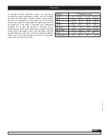
Ratio

1:1

1:1

1:1

Maximum free flow

10 gal/min  (38 l/min)

13.21 gal/min (50 l/min)

22.7 gal/min (100 l/min)

Delivery per stroke

2.37 oz (0,07 l)

3.38 oz (0,1 l)

32 oz (0,25 l)

Air pressure operating 
range 

43.51 to 100 psi  (3 a 7 bar)

43.5 psi - 100 psi  (3 a 7 bar)

43.5 psi - 100 psi (3 a 7 bar)

Solid in suspension max 
size

0.12 in (3 mm)

0.12 in (3 mm)

0.16 in (4 mm)

Maximum suction head

13.2 ft (4 m) dry
26.25 ft (8 m) wet

19.69 ft (6 m) dry
26.25 ft (8 m) wet

14.76 ft (4,5 m) dry
22.97 ft (7 m) wet

Weight 

4.85 lb  (2, 2 kg)

7.72 lb (3,5 kg) metallic
6.17 lb (2,8 kg) plastic

15.87 lb (7,2 kg) metallic
14.33 lb (6,5 kg) plastic

Fluid inlet (single inlet)

1/2" NPT (F)

1/2” NPT (F) and fl ange
1/2” BSP (F) and fl ange-DEF

1” NPT (F) and fl ange
1” BSP (F) and fl ange-DEF

Fluid inlet (double inlet)

2 x 3/8" NPT (F) 

2 x 3/8" NPT (F) 

_

Fluid outlet

1/2" NPT (F) 

1/2” NPT (F) and fl ange
1/2” BSP (F) and fl ange-DEF

1” NPT (F) and fl ange
1” BSP (F) and fl ange-DEF

Air inlet

3/8" NPSM (F)

3/8" NPSM (F)

3/8" NPSM (F)

Wetted materials 

See model specifi cations

See model specifi cations   

See model specifi cations   

Noise level

80 db

80 db

80 db

Temperature range (see 
material temperature 
range on page 2)

0 - 158 ºF (0 - 70 ºC)

0 - 158 ºF (0 - 70 ºC)

0 - 158 ºF (0 - 70º C)

1/2" DOUBLE DIAPHRAGM PUMP CF10 (10 gal/min)
1/2" DOUBLE DIAPHRAGM PUMP CF15 (13.21 gal/min)
1" DOUBLE DIAPHRAGM PUMP CF30 (22.7 gal/min)

Operation and maintenance 
manual

CF10 
1120-029

CF15
1120-025
1120-027
1120-023
1120-028

CF30
1120-024
1120-026
1120-031

Technical data 

1

Warnings and cautions 

2

Description 2
Capacity curves 

3

Dimensions 4
Installation 5
Operating instructions 

6

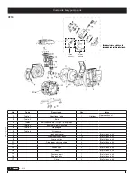
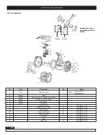
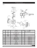
Exploded views:

CF10  

CF15 Polypropylene 

8

CF15 Metallic 

9

CF30 10

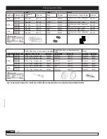
Repair kits / Wetted parts  11
Troubleshooting 12
Maintenance guide 

14

Technical data

* (oz,ft,gal/min) all in EEUU units

Product customization

CODES:

Summary of Contents for CF10

Page 1: ...t 2 x 3 8 NPT F 2 x 3 8 NPT F _ Fluid outlet 1 2 NPT F 1 2 NPT F and ange 1 2 BSP F and ange DEF 1 NPT F and ange 1 BSP F and ange DEF Air inlet 3 8 NPSM F 3 8 NPSM F 3 8 NPSM F Wetted materials See m...

Page 2: ...f explosion if used 1 1 1 trichloroethane methylene chloride or other halogenated hydrocarbon solvents with aluminium wetted materials It could cause serious injury and property damage Inside the pump...

Page 3: ...ributes the air from one chamber to the other thus a reciprocating movement of the diaphragms is created With each stroke fluid is discharged by one of the diaphragms whilst the opposite diaphragm suc...

Page 4: ...9 3 53 1 76 0 Nl min SCFM 410 250 300 350 200 150 100 50 0 8 82 10 58 12 35 14 12 14 47 400 7 06 5 29 3 53 1 76 0 Nl min SCFM 490 350 400 450 300 250 200 150 100 50 0 8 82 10 58 12 35 14 12 15 88 12 3...

Page 5: ...mm 145 mm 41 mm CF15 A B C D E F G 6 14 6 3 6 57 4 13 4 8 0 31 5 75 156 mm 160 mm 167 mm 105 mm 122 mm 8 mm 146 mm I J J K L M N 2 76 1 2 NPT 1 2 BSP 5 91 3 8 NPSM 0 94 M6 70 mm 1120 023 1120 027 112...

Page 6: ...the inlet This is the best possible installation when you need to evacuate the liquid from the drum or tank or when working with viscous fluids Not recommended for hazardous fluids Self priming Pump i...

Page 7: ...or close the valve on the air supply side of the auxiliary equipment Close the discharge valve on the discharge side then begin to slowly open the drain valve and discharge pressure fluid Open the ai...

Page 8: ...Diaphragm cover 2 Not sold as a kit 8 Diaphragm cover bolts 12 Not sold as a kit 9 Pump shields 2 Not sold as a kit 11 Diaphragm cover washers 4 Not sold as a kit 12 Valves cap bolts 8 Not sold as a...

Page 9: ...r sensor 7 Diaphragm cover 2 Not sold as a kit 8 Diaphragm cover bolts 16 Not sold as a kit 9 Pump shields 2 Not sold as a kit 10 Diaphragm cover nuts 16 Not sold as a kit 11 Diaphragm cover washers 4...

Page 10: ...aphragms 6 Table 6 Air sensor 7 Diaphragm cover 2 Not sold as a kit 8 Diaphragm cover bolts 16 Not sold as a kit 9 Pump shields 2 Not sold as a kit 10 Pump shield bolts 8 Not sold as a kit 12 Valves c...

Page 11: ...Diaphragm cover 2 Not sold as a kit 8 Diaphragm cover bolts 20 Not sold as a kit 10 Diaphragm cover nuts 7 Not sold as a kit 12 Diaphragm cover washers 12 Not sold as a kit 13 Valves caps 2 Not sold...

Page 12: ...el Viton Polypropyl ene 833234 Table 4 See note 1 at the bottom of the page Table 5 See note 1 at the bottom of the page Table 6 Pump size Balcrank code Bushing Seals Shaft Kit code Diaphragms Kit cod...

Page 13: ...quipment clogged Check and clean the air line Valve discharge side drive will not open normally Adjust the discharge valve discharge side The air mixes with the fluid Replenish fluid and check the con...

Page 14: ...Replace directional valve components No start up and is leaking air without cycles Cause Recommended measure Stiff air sensors Change air sensor Worn directional valve Replace Troubleshooting Fluid is...

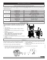
Page 15: ...PLY OF THE PUMP IT IS NOT NECESSARY TO REMOVE THE PUMP FROM THE FLUID LINE 1 Close fluid valves 2 Drain the fluid inside the pump Anticipate a drainage of fluid from inside the pump 3 Remove the direc...

Page 16: ...Install a new set of valves according to these assembly drawings Ensure that the ball guides are assembled as shown in the figure below and tighten the screws with a maximum torque see torque table p...

Page 17: ...17 A 11 16 SB 1145 2016_11_4 8 10 Comments...

Page 18: ...k Corporation Weaverville NC 28787 800 747 5300 800 763 0840 Fax www balcrank com 2016_11_4 8 10 Balcrank Corporation SERVICE BULLETIN SB1145 Revision A 11 16 Revision Log Rev A New release replaces S...

Reviews: