background image

ENGLISH

Vulcan Series

Operator Manual

www.bandg.com

Summary of Contents for Vulcan Series

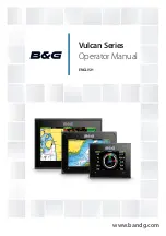
Page 1: ...ENGLISH VulcanSeries Operator Manual www bandg com...

Page 2: ......

Page 3: ...ated to or has been translated from another language Translation In the event of any conflict between any Translation of the Documentation the English language version of the Documentation will be the...

Page 4: ...oFree INSIGHT GENESIS Insight Genesis StructureMap StructureMap StructureScan StructureScan StructureScan HD StructureScan HD Copyright Copyright 2016 Navico Holding AS Warranty The warranty card is s...

Page 5: ...e for operating Vulcan Series units It assumes that all equipment is installed and configured and that the system is ready to use The manual assumes that the user has basic knowledge of navigation nau...

Page 6: ...emory Use the menu options and on screen buttons to maneuver in the PDF file as described below Search Goto page Page Up and Down Select the relevant panel button Scroll pages Drag finger on the scree...

Page 7: ...n currently on this unit can be found in the About dialog The About dialog is available in the System Settings For information regarding upgrading your software refer to Software upgrades on page 184...

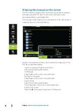
Page 8: ...8 Preface Vulcan Series Operator Manual...

Page 9: ...Man Overboard waypoint 23 Screen capture 24 Customizing your system 24 Customizing the Home page wallpaper 24 Adjusting panel size 25 Password protection 26 Adding new favorite pages 26 Edit favorite...

Page 10: ...with the autopilot 62 Navigation settings 64 SailSteer panel 65 Selecting data fields for the SailSteer panel 65 Sail Time calculations 65 SailSteer overlay 67 Race panel 67 Display options 67 Start L...

Page 11: ...rn pattern steering 92 Using the Vulcan in an AP24 AP28 system 92 Using the autopilot in an EVC system 93 Autopilot settings 97 Radar 97 The radar panel 98 Dual radar 98 Radar overlay 99 Radar operati...

Page 12: ...ing waypoints 126 Viewing StructureScan history 127 Setting up the StructureScan image 128 Advanced StructureScan settings 130 StructureMap 130 The StructureMap image 130 Activating Structure overlay...

Page 13: ...stomizing the Instruments panel 157 Audio 157 Enabling audio 158 SonicHub 2 161 The Audio panel 163 Setting up the audio system 164 Operating the audio system 164 Favorite channels 164 Sirius radio No...

Page 14: ...Demo mode 182 Simulator source files 183 Advanced simulator settings 184 Maintenance 184 Preventive maintenance 184 Cleaning the display unit 184 Cleaning the media port door 184 Checking the connect...

Page 15: ...ion 2 Applications Select a button to display the application as a full page panel Press and hold a button to display pre configured split page options for the application 3 Close button Select to exi...

Page 16: ...cessed from the Home page 1 Application panel 2 Instrument bar Navigation and sensor information The bar can be turned off and it can be configured by the user 3 System controls dialog Quick access to...

Page 17: ...ng the selected application combined with each of the other panels Note The number of pre configured split pages cannot be changed and the pages cannot be customized or deleted Access a pre configured...

Page 18: ...elView 7 or VesselView 4 gateway device is present on the network The engine supplier icon appears on the Home page when a device is available FUSION Link integration The FUSION Link devices appear as...

Page 19: ...n The unit integrates with B G s H5000 Instrument and Autopilot system The H5000 icon will be available in the Tools panel on the Home page when an H5000 system is available on the network Separate do...

Page 20: ...the System Controls dialog Activating functions Select the icon of the function you want to set or toggle on or off For those functions that toggle on and off a highlighted icon indicates the function...

Page 21: ...ght for low light conditions Note Details on the chart may be less visible when the Night mode is selected Locking the touchscreen You can temporarily lock a touchscreen to prevent accidental operatio...

Page 22: ...celling the entry A dialog can also be closed by selecting the X in the dialog s upper right corner Selecting pages and panels Selecting a page Select a full page panel by selecting the relevant appli...

Page 23: ...tion to the initial MOB waypoint Navigation to subsequent MOB waypoints needs to be done manually Cancel navigation to MOB The system continues to display navigational information towards the MOB wayp...

Page 24: ...as the wallpaper it is automatically copied to the Wallpaper folder Adjusting panel size You can change the panel size for an active split page The panel size can be adjusted for both favorite pages a...

Page 25: ...er the correct PIN code is entered all of them can be accessed without re entering the PIN code Settings activated from the Tools panel or System Controls dialog Alarms activated from the Tools panel...

Page 26: ...4 Save the page layout The system displays the new favorite page and the new page is included in the list of favorite pages on the Home page Edit favorite pages 1 Select the edit icon in the Favorite...

Page 27: ...e activate the instrument bar icon to toggle the bar on and off Select a predefined activity bar 1 Select the MENU button to open the menu 2 Select Bar 1 or Bar 2 and then a predefined activity bar Pr...

Page 28: ...ace waypoints and display AIS targets The Chart panel 1 MOB Man Over Board mark 2 Vessel with extension line extension line is optional 3 Waypoint with Laylines 4 North indicator 5 Route 6 Grid lines...

Page 29: ...e In this manual all possible chart menu options are described These options vary depending on the chart you are using Note The system does not automatically switch to embedded cartography if the char...

Page 30: ...n Vessel symbol When the system has a valid GPS position lock the vessel symbol indicates vessel position If no GPS position is available the vessel symbol includes a question mark Chart scale Chart r...

Page 31: ...n so that you can maximize your view ahead Displaying information about chart items When you select a chart item a waypoint a route or a target basic information for the selected item is displayed Sel...

Page 32: ...tween the vessel s current location and the cursor position GoTo cursor You can navigate to a selected position on the image by positioning the cursor on the panel then using the Goto Cursor option in...

Page 33: ...vessel position The grey icon follows the vessel as the vessel moves while the blue icon remains at the position given when you activated the function You terminate the measuring function by selectin...

Page 34: ...the 3D chart You can move the chart in any direction by selecting the Pan icon and then panning in the desired direction Select the Return to vessel menu option to stop panning and to center the chart...

Page 35: ...and C MAP charts All possible menu options for Insight and C MAP charts are described below The features and menu options available can vary depending on the charts you use This section shows menus f...

Page 36: ...han or equal to 6 knots yellow greater than 1 knot and less than or equal to 2 knots or green equal to or less than 1 knot depending on the current in that location If there is no current 0 knots this...

Page 37: ...ry High resolution bathymetry Enables and disables higher concentration of contour lines Insight and C MAP view options Chart detail Full All available information for the chart in use Medium Minimum...

Page 38: ...rea as an overlay on the chart The availability of such photos is limited to certain regions and cartography versions You can view photo overlays in either 2D or 3D modes NoPhotooverlay Photooverlay l...

Page 39: ...sets the limit at which depths will be drawn without blue shading Depth filter Filters out depth values shallower than the selected depth filter limit Shading Shades different areas of the seabed dep...

Page 40: ...rts Navionics specific chart options Orientation Look ahead 3D and change Chart source previously described in this section are common for all chart types Community edits Toggles on the chart layer in...

Page 41: ...n Dynamiccurrentinformation The following icons and symbology are used Current speed The arrow length depends on the rate and the symbol is rotated according to flow direction Flow rate is shown insid...

Page 42: ...tain regions and cartography versions You can view photo overlays in either 2D or 3D modes NoPhotooverlay Photooverlay landonly FullPhotooverlay Photo transparency The Photo transparency sets the opaq...

Page 43: ...eaning that if the chart only contains 5 meter intervals for contour lines the shading is rounded to the nearest available contour line NoDepthhighlightrange Depthhighlightrange 6m 12m Shallow water h...

Page 44: ...f geographical layer information Safety depth The Navionics charts use different shades of blue to distinguish between shallow and deep water Safety depth based on a selected limit is drawn without bl...

Page 45: ...eight must be input to use the autorouting and easy routing features Range Rings The range rings can be used to present the distance from your vessel to other chart objects The range scale is set auto...

Page 46: ...l heading is based on information from the active heading sensor and the COG is based on information from the active GPS sensor Laylines Configures the options for laylines on the chart and on the Sai...

Page 47: ...lculates the tidal effect of the boat based on COG and applies this information to the laylines Overlapped Extends the laylines beyond the tack gybe intersection Length Sets the length of the laylines...

Page 48: ...ues for different true wind speeds Accurate table information gives the system a better basis for creating target laylines Limits Sets the maximum tack gybe time period to either side of the laylines...

Page 49: ...art when a 2D and a 3D chart are shown side by side Pop up information Selects whether basic information for chart items is displayed when you select the item Grid lines Turns on off viewing of longit...

Page 50: ...a waypoint at a selected location by positioning the cursor on the panel and then selecting the new waypoint option in the menu In the Chart and Nav panels you can save a waypoint at the vessel positi...

Page 51: ...the Delete menu option when the waypoint is activated You can also delete waypoints from the Waypoints tool on the Home page You can delete MOB waypoints the same way Waypoint alarm settings You can...

Page 52: ...epoints on the chart panel until the route is completed 5 Save the route by selecting the save option in the menu Edit a route from the chart panel 1 Select the route to make it active 2 Select the ro...

Page 53: ...outepoints on a new route or open an existing route for editing 2 Select Autorouting followed by Entire Route if you want the system to add new routepoints between the first and the last routepoint of...

Page 54: ...examples Entire route option used when first and last route points are selected Firstandlastroutepoint Resultafterautomaticrouting Selection option used for autorouting part of a route Tworoutepointss...

Page 55: ...ute or add multiple waypoints to an existing route 1 Make a note of the waypoints you want to bulk enter You do not have to enter the full waypoint ID just enough of it to distinguish it 2 Select Rout...

Page 56: ...the items it did not find 8 Optional Give the route a name by selecting the system given name and use the virtual keyboard to enter the name 9 Select save Converting Tracks to Routes You can convert...

Page 57: ...el allowing you to retrace where you have travelled Tracks can be converted to routes from the Edit dialog From the factory the system is set to automatically track and draw the vessel s movement on t...

Page 58: ...the recording You can select to position track points based on time settings distance or by letting the system position a waypoint automatically when a course change is registered Note The Tracks opt...

Page 59: ...s The Waypoints Routes and Tracks dialogs give access to advanced edit functions and settings for these items The dialogs are accessed from the Tools panel on the Home page Waypoints Routes and Tracks...

Page 60: ...rsor at the selected destination on the panel and then select the Goto Cursor option in the menu Note The Goto Cursor menu option is not available if you are already navigating Navigate a route You ca...

Page 61: ...udes an option for cancelling the navigation Navigating with the autopilot When you start navigation on a system with autopilot functionality you are prompted to set the autopilot to navigation mode I...

Page 62: ...e north south or along the equator Rhumb lines are tracks of constant bearing It is possible to travel between two locations using Rhumb line computation but the distance would usually be greater than...

Page 63: ...local magnetic variation Datum Most paper charts are made in the WGS84 format which also is used by the Vulcan If your paper charts are in a different format you can change the datum settings accordin...

Page 64: ...er of data fields included in the panel is dependent on available panel size 1 User configurable data fields 2 Vessel heading 3 COG Course Over Ground 4 Apparent wind 5 Port and starboard laylines 6 M...

Page 65: ...select info 5 Repeat the steps to change other instrument fields 6 Save your settings by selecting the save option in the menu Sail Time calculations The system calculates the time and distance to a w...

Page 66: ...y again Note If the Look ahead menu option is selected then the Heading up orientation must also be selected in order to display the SailSteer overlay If the Look ahead menu option is not selected the...

Page 67: ...can display a race start line overlaid on the Chart panel The start line data can be displayed in the Instrument page If you have an H5000 CPU on your network start line data is calculated by the H50...

Page 68: ...rees and distance the biased end will give Start line end not set position not recorded Start line end set position recorded Start line end stale historic start line position Start line end becomes st...

Page 69: ...t line is a line between the port and starboard end points Note If you have an H5000 CPU on your network the start line information between the MFD and the H5000 is shared The start line data numbers...

Page 70: ...ts by pinging requires maneuvering the boat to each end of the start line and then pinging Note Before setting the start line position using the ping method it is important that the Bow off set is upd...

Page 71: ...end point The start line end points are set and can be viewed on the Chart panel and Start line panel Setting end points at coordinates Select the Set coordinate Port and then the Set coordinate Star...

Page 72: ...tart line 2 Square wind line drawn from biased start line end perpendicular to True Wind Direction 3 Distance perpendicular behind line 4 Boat drawn to scale 5 Distance to starboard end of start line...

Page 73: ...easurements in boat lengths can give a clearer indication of the distance from your boat to the start line Show layline grids Select Grid to show layline grids in the start line diagram The grid is a...

Page 74: ...u can start and stop the timer reset it sync it and specify a start value You can display the Race timer from the Race panel menu or by selecting Trip Calculator from the Tools panel The Timer set val...

Page 75: ...r shall use to count down to the start time of the race The timer starts counting down when you select Start Start Stop timer The timer can be started at any time by selecting Start If a time value is...

Page 76: ...start trip is selected the Trip Log records your time and mileage from the moment the countdown timer begins counting up from zero Rolling timer When Rolling timer is selected the timer restarts the...

Page 77: ...attens out at the point the data was lost When the data becomes available again a dashed line joins up the two points showing an average trend line bridging the missing data Selecting data Each data f...

Page 78: ...to help you understand recent changes in wind speed and direction The Wind Plot panel includes wind direction and wind speed The graphics are configured vertically with the newest data being displaye...

Page 79: ...g An autopilot is a useful navigational aid but DOES NOT replace a human navigator Warning A physical standby key should be available for the autopilot Activating the autopilot You activate the autopi...

Page 80: ...r autopilot control unit Autopilot pop up You control the autopilot from the autopilot pop up The pop up has a fixed position on the page and it is available for all pages except when an Autopilot pan...

Page 81: ...Turnpatternselection Autopilot tile in Instrument bar You can select to show the autopilot tile in the Instrument bar If the autopilot pop up is turned off you can turn it on by selecting the tile in...

Page 82: ...standby key Non Follow Up NFU Power steering In NFU mode you use the port and starboard arrow buttons in the autopilot pop up to control the rudder The rudder will move as long as the button is press...

Page 83: ...eading tile in the autopilot pop up and then entering the desired heading value An immediate heading change takes place The new heading is maintained until a new heading is set Heading capture When th...

Page 84: ...the original heading due to current and or wind the vessel follows the line with a crab angle 1 Turn the vessel to the desired heading 2 Activate the NoDrift mode The autopilot draws an invisible bear...

Page 85: ...reject this request you can start NAV mode from the autopilot mode menu When NAV mode is initiated the autopilot automatically keeps the vessel on the leg When the vessel reaches the arrival circle fo...

Page 86: ...oint circle when creating the route X axis Boat speed in knots Y axis Arrival circle radius in 1 100 Nm Example With the speed of 20 knots you should use a waypoint circle with radius 0 09 Nm Note The...

Page 87: ...ut in calm sea conditions with light wind to find out how it works on your boat Due to a wide range of boat characteristics from cruising to racing boats the performance of the tack function may vary...

Page 88: ...waves can yaw the boat into an unwanted gybe this can be hazardous for both the crew and the mast The gybe prevent function is activated when the actual apparent wind angle becomes greater than 175 o...

Page 89: ...ct Autopilot standby in the System Controls dialog to return to STBY mode and manual steering Turn variables The turn steering options except the C turn have settings that you can adjust before you st...

Page 90: ...g distance Square turn Makes the vessel automatically turn 90 after having travelled a defined leg distance At any time during the turn you can change the main heading and the distance of the leg unti...

Page 91: ...our steering to follow the bottom sloping to starboard or to port Portoption depthdecreasestoport Starboardoption depthdecreasestostarboard The following parameters are available for depth contour tra...

Page 92: ...ons The AP24 AP28 includes a Remote Lock function that disables autopilot control from other units A locked control unit is indicated with a key symbol in autopilot controller pop up When the remote l...

Page 93: ...off when the cursor is active on the panel Locking autopilot operation from a unit You can lock a unit to prevent unauthorized operation of the autopilot When the unit is locked it is indicated with...

Page 94: ...n performing a tack in WIND mode the rate of turn tack time can be adjusted This gives single handed sailors time to handle the boat and the sails during a tack A turn performed without shifting wind...

Page 95: ...onse By default the system switches between HI LO parameter set based on speed motor boats or speed and wind sail boats You can however manually select which parameter set that shall be used HI or LO...

Page 96: ...Installation Used for autopilot installation and commissioning See the separate Vulcan Installation manual 96 Autopilot Vulcan Series Operator Manual...

Page 97: ...lso be displayed as an overlay on a chart panel For more information see Chartoverlay on page 35 Note Radar overlay requires data from a heading sensor or compass to ensure proper orientation with the...

Page 98: ...Radar application button on the Home page or by creating a favorite page with two radar panels Selecting the radar source You specify the radar in the Radar panel by selecting one of the available ra...

Page 99: ...odes The radar s operational modes are controlled from the Vulcan unit The following modes are available Off The power to the radar scanner is turned off Standby The power to the radar scanner is on b...

Page 100: ...ments from the panel select Clear cursor or press the X key GoTo cursor You can navigate to a selected position on the image by positioning the cursor on the panel then using the Goto Cursor option in...

Page 101: ...smaller vessels to be seen in the leeward direction of the sea clutter The GAIN of the radar receiver is increased dynamically during the sweep in the leeward direction for increased target sensitivit...

Page 102: ...increased too much as this may filter out real targets Advanced radar options Noise Rejection Broadband 4G radar only The Noise Rejection control sets the amount of noise filtering applied by the rada...

Page 103: ...ol the target discrimination of the radar separation between objects is more prominent Fast scan Broadband Radar only Sets the speed of the radar antenna rotation This option gives faster target updat...

Page 104: ...s start to appear again unless you switch them off as described above The radar palette Different colors palettes can be used to represent detail on your radar panel Radar orientation Radar orientatio...

Page 105: ...Look Ahead Moves the radar PPI center to the bottom of the panel to maximize the view ahead Offset Allows you to move the PPI center to any location on the radar panel 1 Select the offset option from...

Page 106: ...ker 1 Ensure that the cursor is not active 2 Activate the menu select EBL VRM then select EBL VRM 1 or EBL VRM 2 The EBL VRM is now positioned on the radar image 3 Select the adjustment option from th...

Page 107: ...ons depend on the guard zone shape 4 Select Adjust to define the settings for the guard zone The values can be set from the menu or by dragging on the radar panel A Bearing relative to the vessel head...

Page 108: ...e target symbols shown below Acquiring MARPA target Typically it takes up to 10 full rotations of the scanner Tracking MARPA target not moving or at anchor Tracking and safe MARPA target with extensio...

Page 109: ...y basic target information Information for the 3 MARPA targets closest to the vessel is also displayed in the data bar When a target is selected detailed information for the target can be displayed fr...

Page 110: ...ctively from the menu Refer to the Radar panel illustration Bearings Used for selecting whether the radar bearing should be measured in relation to True Magnetic North T M or to your relative heading...

Page 111: ...us of the ring is the same as the closest point of approach as set in the Dangerous Vessels dialog Refer to Defining dangerousvessels on page 154 An alarm triggers if a vessel is tracking into your sa...

Page 112: ...vessel allowing you to detect fish and examine the structure of the sea floor The Echosounder image 1 Depth 2 Temperature 3 Frequency and Zoom scale 4 Bottom 5 Zoom buttons 6 Depth range scale 7 Inst...

Page 113: ...to a target to mark a position and to select targets By default the cursor is not shown on the image When you position the cursor on the image the screen pauses the depth at the cursor position is sho...

Page 114: ...r on the second measuring point A line is drawn between the measuring points and the distance is listed in the Cursor Information panel 4 Continue selecting new measuring points if required You can us...

Page 115: ...dual Echosounder panels from the Home page Frequency is the tone the transducer transmits Transducers are designed to operate on different frequencies as the various frequencies have different qualiti...

Page 116: ...more echoes are displayed in the color at the strong return end of the scale DownScan options Provides options for specifying the DownScan image This menu option is available when Overlay downscan is...

Page 117: ...e scrolling speed of the image on the screen A high scroll speed updates the image fast while a low scroll speed presents a longer history Note In certain conditions it may be necessary to adjust the...

Page 118: ...ols Save to Select whether the recording is to be saved internally or to a memory card in the card reader Bytes per sounding Select how many bytes per seconds that are to be used when saving the log f...

Page 119: ...er data Note If you have selected the Upload to Insight Genesis option and are connected to a wireless hotspot your recorded files are transmitted to Insight Genesis when you select Stop Viewing the r...

Page 120: ...m lock The bottom lock mode is useful when you want to view echoes close to the bottom In this mode the left side of the panel shows an image where the bottom is flattened The range scale is changed t...

Page 121: ...play shows the range that is magnified and displayed on the left side If you increase the zooming factor the range is reduced You see this as reduced distance between the zoom bars You can move the zo...

Page 122: ...og file is displayed as a paused image and you control the scrolling and display from the menu You can use the cursor on the image measure distance and set view options as on a live Echosounder image...

Page 123: ...jects within the set depth range Installation Used for installation and setup See the separate Vulcan Installation manual ForwardScan Installation Used for ForwardScan installation and setup Refer to...

Page 124: ...detail with SideScan while DownScan provides detailed images of structure and fish directly below your boat The StructureScan page is accessed from the Home page when the transducer is connected The S...

Page 125: ...you position the cursor on a SideScan image the screen pauses and the cursor information window is activated On a SideScan image the left right distance from the vessel to the cursor are shown at the...

Page 126: ...he distance is listed in the Cursor Information panel 4 Continue selecting new measuring points if required You can use the menu to re position the start point and the end point as long as the measuri...

Page 127: ...sets the range depending on the water depth Preset range levels You can select between several preset range levels StructureScan frequencies StructureScan supports two frequencies 455 kHz provides id...

Page 128: ...image and if you are using the cursor to measure a distance between 2 elements on the image Advanced StructureScan settings TVG Wave action boat wakes and temperature inversions can cause onscreen cl...

Page 129: ...Scan data You can record StructureScan data and save the file internally in the Vulcan unit or onto memory card as described in StartRecording echosounderdata on page 117 StructureScan Vulcan Series O...

Page 130: ...th a traditional SideScan panel You move around in the chart as usual when you have a Structure overlay Activating Structure overlay 1 Turn on Structure overlay from the chart menu The chart menu is i...

Page 131: ...but the width and the length of the image history is increased Note Live mode does not save any data If the unit is turned off all recent data is lost Saved files When Saved files are selected the Str...

Page 132: ...panel When StructureScan data is being recorded there is a flashing red symbol and a message appears periodically at the bottom of the screen Note The message includes information about file size Kee...

Page 133: ...hen Structure overlay is enabled Not all options are available when saved StructureMap files are used as the source Unavailable options are greyed Range Sets the search range Transparency Sets the opa...

Page 134: ...umps engine vibration and air bubbles can clutter the sonar screen The noise rejection option filters the signal interference and reduces on screen clutter Clear live history Clears existing live hist...

Page 135: ...or installation instructions refer to the ForwardScan transducer installation manual Warning Do not rely on this equipment as your principle source of navigation or hazard detection Warning Do not use...

Page 136: ...n sonar logs Pause Pauses forward looking Echosounder transmissions ForwardScan view options Palette Several display palettes are available for a variety of water conditions History ratio Controls how...

Page 137: ...depth and the underwater objects Heading extension You can use the heading extension to monitor ForwardScan on the chart panel Heading extension colors are based on the ForwardScan alarm values Forwa...

Page 138: ...ForwardScan installation dialog Critical forward range and Critical depth Critical Forward Range and Critical Depth are user selected thresholds that define a critical zone forward of your vessel 138...

Page 139: ...cted Critical Forward Range and Critical Depth values Note To receive Critical Zone alerts enable ForwardScan alarm in the Alarm settings dialog For more information about enabling alarms refer to Ala...

Page 140: ...e ways in which the offset can be entered Before setting the offset measure the distance from the transducer to the lowest point of the boat in the water or from the transducer to the water surface A...

Page 141: ...built in wireless functionality is described in your system s Installation Manual Connect and disconnect from a wireless hotspot To connect to a wireless hotspot select the Wireless option in the Sys...

Page 142: ...om their relevant Application store When remote control is accepted the active page is mirrored to the wireless device Note To use smartphones and tablets to view and control the system wireless funct...

Page 143: ...before following this procedure 1 Set the internal wireless to Access Point mode To do this select the Wireless devices page in the Wireless settings dialog and then select the unit s Internal Wirele...

Page 144: ...ile you want to upload from the Files panel and select the upload to Insight Genesis option Note You must be connected to a wireless hotspot to upload recorded log files to Insight Genesis Note Record...

Page 145: ...e access Wireless devices This dialog shows the internal wireless and any connected WIFI 1 devices as well as their IP and channel number Selecting the internal wireless or a WIFI 1 device provides ad...

Page 146: ...range or you can select to delete it Advanced Initiates the Iperf and DHCP Probe tools that help in fault finding and setting up the wireless network Note Iperf and DHCP Probe are tools provided for d...

Page 147: ...this feature an important tool for safe travelling and collision avoidance You can set alarms to notify you if an AIS target gets too close or if the target is lost AIS target symbols The system uses...

Page 148: ...argets by using the Find option in the Tools panel From a chart panel you can search for AIS targets by using the Find option in the menu If the cursor is active the system searches for vessels around...

Page 149: ...ll dialog is closed when the connection is established AIS SART When an AIS SART Search and Rescue beacon is activated it starts transmitting its position and identification data This data is received...

Page 150: ...bearing from your vessel You have the following options Ignore the alarm The alarm is muted and the message closed The alarm does not reappear Note If you ignore the alarm the AIS SART icon remains v...

Page 151: ...arms You can define several alarms to alert you if a target shows up within predefined range limits or if a previously identified target is lost Dangerous vessel Controls whether an alarm will be acti...

Page 152: ...ddressed messages from AIS and DSC vessels It is also important to have the MMSI number entered to avoid seeing your own vessel as an AIS target on the chart Note The Vessel message option in the alar...

Page 153: ...to indicate the distance the vessel will move in the selected time period If no options are turned on for This vessel then no extension lines are shown for your vessel Your own vessel heading informa...

Page 154: ...rse indication The extension line can be used to indicate speed and course for targets either as absolute true motion in the chart or relative to your vessel A different line style is used on the exte...

Page 155: ...ds by selecting the left and right arrow buttons on the panel You can also select the dashboard from the menu Vesseldashboard Navigationdashboard Anglerdashboard Note Additional dashboards can be acti...

Page 156: ...Select the gauge you want to change Selected gauge is indicated with a colored background 4 Select information to be displayed configure limits and eventually change the source for the information 5 S...

Page 157: ...ed subscription package SiriusXM radio is only available in certain locations For more information refer to www siriusXM com SiriusXM audio is not available on 5 and 7 units Before you can start using...

Page 158: ...rmation dialog Configure Select to configure the device Upgrade Updates the device software Note A USB memory stick with the software upgrade must be plugged into the device Periodic software updates...

Page 159: ...ant to pair to from the list of available devices and then select Pair The SonicHub 2 connects to the paired device Connecting and disconnecting paired devices The SonicHub 2 automatically connects to...

Page 160: ...cHub 2 supports streaming music from Pandora from an Android device over Bluetooth or IOS device over USB and Bluetooth Note You must be in a valid location to use Pandora Refer to the Pandora website...

Page 161: ...ibed later in this chapter 1 Audio source 2 Audio control buttons 3 Audio tile 4 Audio tools Audio control buttons Icon Tuner VHF DVD Playback Select to display the list of available sources Select to...

Page 162: ...me slider Audio tools Icon Tuner VHF Playback Signal strength N A N A N A N A Select to toggle on off repeat function The icon is colored when the function is active N A N A Select to toggle on off sh...

Page 163: ...es Master volume control By default the volume for all speaker zones are adjusted when you adjust the volume You can define which zones will be altered when you increase decrease the volume Selecting...

Page 164: ...tuner or VHF channel is tuned in you can add the channel to your favorite list The favorite channels can be viewed selected and deleted from within the Favorite list You page through favorite channels...

Page 165: ...d is indicated by a combination of small and large barbs at the end of the wind tail Zero knots Indeterminate wind direction Small barb 5 knots Large barb 10 knots Arrow barb 50 knots If a combination...

Page 166: ...Refer to DisplayingGRIBweatherasoverlay on page 167 The file can be imported from any location that can be seen in the file manager Note GRIB data that is imported overwrites the GRIB data in memory...

Page 167: ...weather data can be displayed as an overlay on your chart panel When the GRIB weather overlay is selected the chart menu increases to show GRIB weather options From this menu you can select which wea...

Page 168: ...d to show the predicted forecast for a specific time and date The time scales vary depending on the file you are using The time shift is shown in brackets in the GRIB information window The time is re...

Page 169: ...ictWindweatherfiles on page 171 Import the file into memory to overlay it on the chart refer to SpecifyPredictWindGRIBoverlayfile on page 174 Download PredictWind files to a memory card connected to a...

Page 170: ...om the Chart settings dialog Select Email and enter your PredictWind login email address Select Password and enter your PredictWind password Automatically download PredictWind weather files The automa...

Page 171: ...is only available if you have turned on GRIB weather overlay on the Chart menu refer to TurnonGRIBweatheroverlay on page 170 and your PredictWind login credentials are entered in the system refer to P...

Page 172: ...n expandable rectangle Drag the rectangle s corner markers to create the area rectangle you want to download GRIB weather for and choose the select menu option After you create your offshore area rect...

Page 173: ...weather observation from the National Oceanic and Atmospheric Administration NOAA of the USA Department of Commerce Available for Offshore GRIB only Wind and Pressure The wind and or pressure data fr...

Page 174: ...rt and which files are available for display Available GRIB files are files downloaded manually or automatically from PredictWind to the Gribs directory If you copy GRIB files from the memory card to...

Page 175: ...es them from the available GRIB files list to the expired GRIB files list Expired files are files where the time of the final forecast has passed Select the Delete expired GRIB files option to delete...

Page 176: ...sages The messages are classified according to how the reported situation affects your vessel The following color codes are used Color Importance Red Critical Orange Important Yellow Standard Blue War...

Page 177: ...the alarm has been removed Disable Disables the current alarm setting The alarm does not show again unless you turn it back on in the Alarms dialog There is no time out on the alarm message or siren T...

Page 178: ...178 Alarms Vulcan Series Operator Manual...

Page 179: ...r delete Tides Displays tide information for the tide station nearest to your vessel Select the arrow panel buttons to change the date or select the date field to access the calendar function Availabl...

Page 180: ...f the unit s internal memory and inserted SD card Viewing files Select a file in the Files panel and then the view file option in the Details dialog Copying files to a card in the card reader You can...

Page 181: ...an also upload your Echosounder logs to be shared on Social Map charts When you log on the system automatically gives you a notification if a new software version is available for your system If an up...

Page 182: ...etc If you tap on the touchscreen when demo mode is running the demonstration pauses After a time out period demo mode resumes and any changed settings are restored to default Note Demo mode is desig...

Page 183: ...Advanced simulator settings The Advanced simulator settings allows for manually controlling the simulator Simulator Vulcan Series Operator Manual 183...

Page 184: ...void any contact with solvents acetone mineral turpentine etc or ammonia based cleaning products as they may damage the anti glare layer or plastic bezel To prevent UV damage to the plastic bezel it i...

Page 185: ...n automatically gathered from the network You can add screenshots and log files that will be attached to the report There is a 20MB limit for the report attachments You can save the report to a memory...

Page 186: ...bits of information these systems store about items User Data file version 3 w depth Should be used when transferring user data from one system to a legacy product Lowrance LMS LCX User data file vers...

Page 187: ...rom where you want to export data 1 Select Export region 2 Drag the boundary box to define the desired region 3 Select the export option from the menu 4 Select the appropriate file format 5 Select Exp...

Page 188: ...stored in the display unit s memory until the data is purged If you have numerous deleted unpurged Waypoints purging may improve the performance of your system Note When user data is purged from the...

Page 189: ...le a checkbox option on or off Show basic information for a selected item Press and hold On any panel with a cursor to activate the cursor assist feature On a panel button to see available split scree...

Page 190: ...Icon Description Pinch to zoom out on the chart or on an image Spread to zoom in on the chart or on an image 190 Touchscreen operation Vulcan Series Operator Manual...

Page 191: ...ing up the system 163 Sirius radio 164 Speaker zones 163 Speakers 163 Audio Panel 161 Audio tools 162 Auto gain 116 Autopilot 79 Activating 79 AP24 28 systems 92 AUTO mode 83 Autopilot pop up 80 Autop...

Page 192: ...r overlay source 99 Selecting chart type 30 Settings 45 Using the cursor 32 Vessel symbol 30 Zooming 30 Charts Symbol 30 Color 116 Connect Smartphone and tablet 142 Wireless hotspot 141 Controller Vie...

Page 193: ...cal Forward Range 138 Critical Zone alarm 138 Heading extension 137 Image 135 Installation 123 Setup 138 Transducer angle 139 Frequency 115 FUSION Link 157 G Gain 115 Go to cursor 32 100 113 125 GoFre...

Page 194: ...osition 60 With autopilot 61 Navigation settings 62 Navionics chart options 40 Noise rejection 117 O Operation Touch 189 Overlay downscan 122 Overlay SailSteer on Chart 65 P Pages Selecting a page 22...

Page 195: ...ecord echosounder data 129 Recording Start recording echosounder data 117 Start recording log data 117 Rhumb lines 62 Routes 52 Autorouting 53 Converting tracks to routes 56 Creating a new route on th...

Page 196: ...uencies 127 Image 124 Noise rejection 134 Pausing the image 128 Preset range levels 127 Range 127 Range lines 128 Recording data 132 Using the cursor 125 View down or side scan 128 View history 126 Vi...

Page 197: ...ings 51 Delete 51 Dialog 59 Edit 51 Moving 50 Saving 50 100 Waypoints routes trails and trips Export 186 Weather 165 Showing weather details 165 Wind barbs 165 Wind plot panel 78 Wind plots 77 Wireles...

Page 198: ...988 11111 002 0980...

Reviews: