Quick Start Guide
Imager-based barcode reader with superior decoding capability in compact housing
This guide is designed to help you set up and install the ABR 3000. For complete information on programming, performance, troubleshooting,
dimensions, and accessories, please refer to the Instruction Manual at
www.bannerengineering.com
. Search for p/n 207637 to view the In-
struction Manual and for p/n 207635 to view the Barcode Manager Software Instruction Manual. Use of this document assumes familiarity with
pertinent industry standards and practices.
WARNING: Not To Be Used for Personnel Protection
Never use this device as a sensing device for personnel protection. Doing so could lead to serious injury or death. This
device does not include the self-checking redundant circuitry necessary to allow its use in personnel safety applications.
A sensor failure or malfunction can cause either an energized or de-energized sensor output condition.
Models
Table 1: ABR 3000 Models
Model
Resolution
Lens
Lighting
Options
Communications
Codes
ABR3009-WSU2
WVGA
(752 × 480 pixels)
9 mm, manual focus
White
Standard
Serial/USB
1D and 2D
ABR3009-WSE2
Serial/Ethernet
1D and 2D
ABR3009-WSU1
Serial/USB
1D
ABR3009-WSE1
Serial/Ethernet
1D
ABR3106-WSU2
1.2 MP
(1280 × 960 pixels)
6 mm, manual focus
Serial/USB
1D and 2D
ABR3106-WSE2
Serial/Ethernet
1D and 2D
ABR3106-WSU1
Serial/USB
1D
ABR3106-WSE1
Serial/Ethernet
1D
ABR3106-WPU2
Polarized
Serial/USB
1D and 2D
ABR3106-WPE2
Serial/Ethernet
1D and 2D
Features
1
11
4
3
5
5
8 7
6
9
10
2
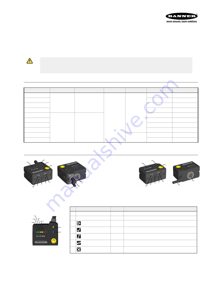
Figure 1. Models with Serial and Ethernet
1. Smart Teach Interface
2. Ethernet Connection LED
3. Power LED
4. Button
5. Internal Illuminators
6. Good Read LED (green)
7. Lens
8. Aiming System Laser Source
9. Focus Adjustment Screw
10. Ethernet Cable
11. Power - Serial - I/O Cable
3
1
4
5
5
8 7
6
11
9
Figure 2. Models with Serial and USB
Indicators
3
4
5
6
7
1
2
Figure 3. Indicators—Top of Device
Indicator
Color
LED Status During Normal Operation
1
Power
Blue
Indicates connection to the power supply
2
Ethernet Connection
Amber
Indicates connection to the Ethernet network
3
READY/Learn
Green
Ready
4
GOOD/Setup
Green
Reading successful
5
TRIGGER/Focus (Aim)
Amber
Reading in progress. Do not trigger a new reading attempt until the cur-
rent attempt finishes
6
COM/Test
Amber
Active result output transmission on the Main serial or USB ports
7
STATUS
Red
No read result
During the reader startup, all of the LEDs turn on for one second.
See
Smart Teach Interface
on page 3 for the colors and meanings of the five LEDs when the reader is in Smart Teach mode.
ABR 3000
Original Document
207636 Rev. A
2018-7-26


