background image

iVu Plus BCR Communications

Instruction Manual

Original Instructions

B_3084221 Rev. C

18 March 2014

Summary of Contents for iVu Plus BCR

Page 1: ...iVu Plus BCR Communications Instruction Manual Original Instructions B_3084221 Rev C 18 March 2014...

Page 2: ...ing 16 4 3 3 Verifying Basic Receive Functionality 16 5 Command Channel Primer 18 5 1 Command Channel Commands 18 5 1 1 Command Flow 18 5 1 2 String Delimiters and Escaping 18 5 1 3 Command Channel Co...

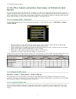
Page 3: ...Industrial Ethernet using Ethernet IP Modbus TCP or PCCC protocols This document will help you to set up the iVu Plus in the desired configuration and provide you with information you will need to co...

Page 4: ...tion data to a remote device Image Export used to export inspection images to a remote device Data export and command channel can be configured for either Ethernet or Serial I O but not both image exp...

Page 5: ...e the running inspection Command Channel Sample Application The iVu Plus BCR installation CD has a Command Channel sample application that provides an easy interface to execute commands In a productio...

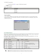
Page 6: ...Windows BMP format that represent all the data in a full Field of View FOV Each exported image is comprised of a header 64 bytes followed by the image data approximately 361K All 16 and 32 bit numeric...

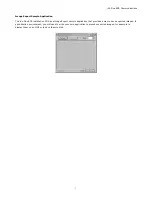
Page 7: ...a Image Export sample application that provides a way to save exported images In a production environment you will need to write your own application to process exported images for example to display...

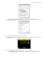
Page 8: ...log select Use the following IP address and make sure that the IP address is 192 168 0 2 and the subnet mask is 255 255 255 0 3 1 2 Windows 7 1 Open Network Connections by clicking on the Start button...

Page 9: ...sk is 255 255 255 0 3 1 3 Sensor Setup for Ethernet Communications 1 Go to Main Menu System Communications Ethernet I O and make sure that the sensor is configured as shown below 2 To enable the comma...

Page 10: ...lon CR CR LF LF CR or ETX c Verify that the iVu receives and transmits data correctly 3 To enable Data Export over Ethernet a Go to Main Menu System Communications Data Export Connection and select Se...

Page 11: ...ll behave in this situation Select Hold READY to ensure that all frames are transmitted In this case the READY signal will remain inactive sensor is busy until the new frame has been added to the chan...

Page 12: ...on the control device Go to Main Menu System Communications Serial I O 3 To enable the command channel over the serial connection a Go to Main Menu System Communications Command Channel Connection and...

Page 13: ...Communications Data Export Connection and select Serial I O from the drop down b Go to Main Menu System Communications Data Export Data To Export and select the inspection data to export c Go to Main...

Page 14: ...ting affects how the sensor will behave in this situation Select Hold READY to ensure that all frames are transmitted In this case the READY signal will remain inactive sensor is busy until the new fr...

Page 15: ...the control device Icon Description Port opened Port closed Indicates that the command has been processed without errors Indicates that the incoming entry is stalled no new bytes or end of frame deli...

Page 16: ...t settings or in the case of Break incorrect cabling 4 3 2 Using the iVu Command Channel Sample Application or a Terminal Program for Testing The easiest way to test that the iVu command channel is co...

Page 17: ...d in a way that does not generate serial hardware errors Verify the settings on both devices match exactly Verifying Basic Transmit Functionality The iVu command channel will only send response frames...

Page 18: ...CR LF LF CR ETX NOTE When data is displayed on iVu screens such as the Port Status screen printable delimiters are displayed as expected Non printable characters such as CR are displayed in hex notat...

Page 19: ..._NOT_RECOGNIZED Refer to Command Channel Error Codes on page 26 for a list of errors 5 2 Conventions Used for Examples There are a number of command channel examples included here and the following ar...

Page 20: ...Modify Barcode Compare Data Using the Command Channel 1 Go to the Main Menu System Sensor Configuration Serial I O 2 Click on the Channel Mode button 3 n the Channel Mode dialog select Command from t...

Page 21: ...mber of the remote display as a string Examples get info companyname x0D x0A OK x0D x0A Banner Engineering Corp x0D x0A get info bootnumber x0D x0A OK x0D x0A 42 x0D x0A get info uptimer x0D x0A OK x0...

Page 22: ...tatus clearsystemerror x0D x0A OK x0D x0A 5 4 4 Trigger Command Group Command Group Item Description Get Trigger Mode The sensor s triggering mode This value must match the modes supported by the sens...

Page 23: ...lly brighten all image pixels This value can be modified using the sensor s touchscreen This remotely modified value is not persisted to the sensors permanent memory The Save operation is required to...

Page 24: ...meNumber This value indicates the latest frame number for the active inspection This value is cleared reset whenever history is cleared This value is cleared reset when the device starts up or is rebo...

Page 25: ...ith the double quote character This value can be modified using the sensor s touchscreen This remotely modified value is not persisted to the sensors permanent memory The Save operation is required to...

Page 26: ...s Multiple values are seperated by the field delimiter The most recent inspection value is used Access to this value requires a valid trigger 5 4 12 BCR_HISTORY Command Group Command Group Item Descri...

Page 27: ...OT_READY Command specified requires sensor to be in the READY state 10920 SENSOR_TYPE_NOT_ACTIVE Command specified belongs to a different sensor type 15000 VALUE_INVALID Text value is invalid unknown...

Page 28: ...channels 4 D data export 4 data export log 15 data export sample application 6 E Ethernet 4 ethernet communications 8 H history command group 24 I image export 4 6 image export sample application 7 I...

Reviews: