background image

DIRECTIONS FOR USE             INSTALLATION INSTRUCTIONS

ECO


60 / 70 / 90 / 100  

EN -13240

 NAME


  OUTPUT     

DESCRIPTION

ECO  60  


9.0 kW 


Stove

ECO  70  

   10.0 kW 


Stove 

ECO  90  

   10.0 kW 


Stove

ECO 100 

   10.0 kW 


Stove

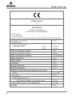
Summary of Contents for ECO 60
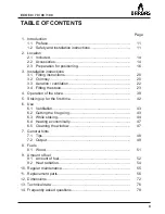
Page 1: ...DIRECTIONS FOR USE INSTALLATION INSTRUCTIONS ECO 60 70 90 100 EN 13240 NAME OUTPUT DESCRIPTION ECO 60 9 0 kW Stove ECO 70 10 0 kW Stove ECO 90 10 0 kW Stove ECO 100 10 0 kW Stove...

Page 2: ......

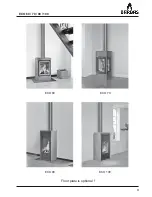
Page 3: ...3 ECO 60 70 90 100 ECO 60 Floor plate is optional ECO 90 ECO 70 ECO 100...

Page 4: ...4 ECO 60 70 90 100...

Page 5: ...mable material Rear 100 mm Side 100 mm Emission combustion products Pass carbon monoxide CO emission 0 10 Escape of hazardous substances Not determined Surface temperature Pass Electrical safety Pass...

Page 6: ...able material Rear 100 mm Side 800 mm Emission combustion products Pass carbon monoxide CO emission 0 04 Escape of hazardous substances Not determined Surface temperature Pass Electrical safety Pass C...

Page 7: ...able material Rear 100 mm Side 100 mm Emission combustion products Pass carbon monoxide CO emission 0 06 Escape of hazardous substances Not determined Surface temperature Pass Electrical safety Pass C...

Page 8: ...mable material Rear 100 mm Side 100 mm Emission combustion products Pass carbon monoxide CO emission 0 06 Escape of hazardous substances Not determined Surface temperature Pass Electrical safety Pass...

Page 9: ...n ventilation 22 3 4 Fitting the stove 23 4 Operation of the stove 39 5 Stoking up for the first time 42 6 Use 6 1 Ventilation 43 6 2 Getting the fire going 43 6 3 While stoking 44 6 4 Heating economi...

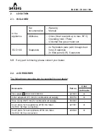
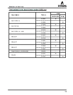
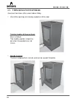
Page 10: ...10 ECO 60 70 90 100...

Page 11: ...liance Pay special attention to furnishings and ornaments around the stove To ensure safe operation the following minimum distances must be maintained between the appliance and any existing side or re...

Page 12: ...mmable fat deposits to be left in the chimney and hastens the chimney becoming clogged Prevent your chimney being soiled from above birds nests etc by fitting a suitable cap to the chimney pot Follow...

Page 13: ...the bottom have not moved Check whether the grate is lying correctly and there are no foreign objects in the ashtray Avoid over loading white burning glow caused for example by lengthy burning with p...

Page 14: ...tom plate with through feed ECO 100 Soapstone hole Soapstone 2x Side panel L R Soapstone N B If any part is missing please contact your dealer Accessorie Part no Color Anthracite Floor plate E ECO 60...

Page 15: ...50 mm Description Part no Color Anthracite Gray Duct 1000 mm 310087 310094 Duct 500 mm 310088 310095 Duct 1000 mm valve 310180 310186 Elbow 90 310093 310100 Elbow 45 310091 310098 Elbow 30 310090 3100...

Page 16: ...of the stove before fitting Check the opening and closing operation of the door Turn the handle all the way down Door is locked This handle position should be set when the appliance is not in use Han...

Page 17: ...and setting of the flue gas flap ECO 60 If necessary the flue gas flap pin can be adjusted ECO 60 Flue gas flap pin Flue gas flap Door open Pin comes forwards Flue gas flap open Door closed Pin is pre...

Page 18: ...18 ECO 60 70 90 100 Check whether the ashtray is completely empty Check the operation of the slider for controlling the combustion air...

Page 19: ...dealer Remove enclosed documents and components from the stove Have the suitability of the area in which the stove is to be placed and the chimney approved by a specialist The stove must have its own...

Page 20: ...iances to a single flue chimney is not allowed 3 2 CHIMNEY Be sure that existing chimneys are completely air tight and in good condition In terms of dimensions the chimney must have a diameter of at l...

Page 21: ...thick walled smoke piping Steel 2 mm See Chapter 2 2 The first pipe connected to the appliance must have a diameter of 150 mm int at both ends This will prevent any condensation from the chimney runni...

Page 22: ...combustion going by drawing in air from the room or directly from outside due to the natural draught of the chimney Combustion air from the living room The air inlet opening 125 mm is found at the rea...

Page 23: ...e independently of the surrounding air in the room where the appliance is located 3 4 FITTING THE STOVE 3 4 1 Connecting the smoke outlet ECO 60 The appliance can make use of either a top or rear conn...

Page 24: ...70 90 100 Assemble the sealing plate to the rear of the combustion chamber of the appliance Assemble the cover plate to the rear of the appliance Attention Ensure that the sealing cord fits properly...

Page 25: ...f the appliance Assembling of the smoke outlet ECO 60 rear connection Install the cast iron flue gas exhaust flue connection ring to the rear of the appliance Attention Ensure that the sealing cord fi...

Page 26: ...stainless steel flues Situate the appliance in such a way that the flue gas outlet is precisely in line under the chimney connection niche pipe in the ceiling top connection or with the chimney connec...

Page 27: ...27 ECO 60 70 90 100 Remove the cover plate at the rear of the appliance Remove the cast iron flue gas exhaust flue connection ring on the top of the appliance...

Page 28: ...the sealing plate at the rear of the combustion chamber of the appliance Install the cast iron flue gas exhaust flue connection ring to the rear of the appliance Attention Ensure that the sealing cor...

Page 29: ...0 70 90 100 Assemble the sealing plate to the top of the combustion chamber of the appliance Place the steel cover plate on top of the appliance Attention Ensure that the sealing cord fits properly al...

Page 30: ...s You can remove any stains on the soapstone with a dry scouring sponge Choose which soapstone top bottom plate will be placed in view on the top of the appliance Soapstone is a natural product That i...

Page 31: ...n the soapstone bottomplate Keep 4 cm free to both left and right Align the appliance with the front soapstone edge Also check whether the appliance with the soapstone bottomplate is level Pack the bo...

Page 32: ...32 ECO 60 70 90 100 Place the supplied brass spread anchors totally 4x in the top of the soapstone side panels and screw the threaded pins into them...

Page 33: ...60 70 90 100 Place the side panels carefully over the two metal pins in the soapstone bottomplate Secure the top with the supplied brackets 2x Check that the panels are completely parallel with the ap...

Page 34: ...34 ECO 60 70 90 100 Assemble the cast iron flue gas exhaust flue connection ring supplied to the top of the appliance Attention Ensure that the sealing cord fits properly all round...

Page 35: ...ECO 60 70 90 100 Fit the soapstone top plate Check whether the top plate is 1 2 mm free all round The appliance is now ready Check whether the smoke outlet top connection is in line with the chimney f...

Page 36: ...l connection ECO 60 Determine the length of pipe required and push this as far as possible into the sliding sleeve before the appliance is placed Once the appliance is placed you can pull the pipe fro...

Page 37: ...37 ECO 60 70 90 100 Connecting direct air supply connection Press the collar ring 125 mm in the opening at the rear of the appliance...

Page 38: ...pe 125 mm between the flexible pipe and the external air supply opening in the wall with if required a movable damper in such a way that the pipe with operating lever is fitted so that the damper can...

Page 39: ...e gas outlet 150 mm top rear connection possibility 6 Convection air escape opening permanent 7 Side panels vermiculite plate Inner lining 8 Grate Primary air supply 9 Ashtray 10 Combustion air supply...

Page 40: ...onvection air escape opening permanent 5 Side panels vermiculite plate Inner lining 6 Grate Primary air supply 7 Ashtray 8 Intake openings combustion air and convection air rear of appliance 9 Combust...

Page 41: ...mm top connection 4 Convection air escape opening permanent 5 Side panels vermiculite plate Inner lining 6 Grate Primary air supply 7 Ashtray 8 Intake openings combustion air and convection air rear...

Page 42: ...g parts are in order and that loose parts such as the retardant plate brake plate flue gas flap interior panels grate etc are in the correct position They may have moved during installation The stove...

Page 43: ...eans that the chimney s capacity to draw in air is limited That is why the air supply has to be assisted by opening the locking ECO 60 and or the door and air supply slider Use dry fine wood and some...

Page 44: ...fire will be burning fiercely You can now top it up with a few larger blocks of wood Turn the locking all the way to the left ECO 60 when these blocks are burning well and close the door Using the ai...

Page 45: ...approximately 45 minutes The flames are then almost no longer visible Do not leave the door open longer than necessary Weather conditions In order to reduce pollution and any other inconvenience we ad...

Page 46: ...sh air The combustion air can namely be drawn from the room where the stove is located Turn on the flue gas fan if the flue is fitted with one Spare parts Any replacement parts must be new original pa...

Page 47: ...Using dry and clean wood as described further in chapter 8 Always ensure even combustion Stoke with the primary air regulator closed To do this place the air supply slider in the centre position The...

Page 48: ...ot and tar in your chimney which unchecked will increase the risk of chimney fire Keep the door shut when the fire is burning Doing so improves the performance of your fire 8 10 times benefiting the e...

Page 49: ...it swept and inspected for damage and leakage 7 2 OUTPUT In practice combustion is all about loss This entails Loss through excess heat leaving the chimney rather than going into the room Loss throug...

Page 50: ...is a problem if your stove is too small In that case it becomes overloaded and burns more wood than heat emitted In this case too the fuel cannot burn completely More to the point there is not enough...

Page 51: ...less heat Examples are spruce pine poplar and linden Unsuitable fuels are Painted bonded chipboard MDF etc or impregnated wood plastic and other flammable waste Stoking a fire with this is completely...

Page 52: ...by overheating Burning one layer of wood can lead to varying outputs When used correctly one load will burn in around 45 minutes Putting in too much wood at once can lead to the appliance being overlo...

Page 53: ...cm perimeter 1 15 kg The maximum burning load is based on a nominal capacity of 10 kW and a efficiency of 77 ECO 90 100 Per filling Calculated per hour for 45 minutes Wood 2 blocks 3 blocks each arou...

Page 54: ...h can theoretically be achieved by burning wood Heat radiation Sort of fuel kWh kg Dry wood average 4 3 The heating value of wood 18 7 MJ kg at 0 humidity is not affected by the sort of wood What does...

Page 55: ...e heating is resumed Replace as necessary Sweep and inspect chimney Annually before heating is resumed Fire hearth interior Check annually Replace panels as necessary Grate Check annually for cracks b...

Page 56: ...vermiculite plate 1 4 Panel rear vermiculite plate 2 5 Panel bottom rear vermiculite plate 1 6 Grate 1 7 Ashtray 1 8 Panel bottom front vermiculite plate 1 9 Door 1 10 Glass 1 11 Retardant plate brake...

Page 57: ...m side right vermiculite plate 1 5 Retardant plate brake plate under vermiculite plate 1 6 Panel bottom rear vermiculite plate 1 7 Grate 1 8 Ashtray 1 9 Panel rear under vermiculite plate 1 10 Panel b...

Page 58: ...ar top vermiculite plate 1 4 Panel side right vermiculite plate 1 5 Retardant plate brake plate under vermiculite plate 1 6 Panel bottom rear vermiculite plate 1 7 Grate 1 8 Ashtray 1 9 Panel rear und...

Page 59: ...culite plate 1 4 Panel side right vermiculite plate 1 5 Retardant plate brake plate under vermiculite plate 1 6 Panel bottom rear vermiculite plate 1 7 Grate 1 8 Ashtray 1 9 Panel rear under vermiculi...

Page 60: ...the appliance including the retardant plates brake plates is made of a heat resistant material vermiculite panels that is very fragile Use a broad flat screwdriver for the careful removal of the vermi...

Page 61: ...plate brake plate by lifting it slightly and removing it sloping to one side Remove the flue gas flap by lifting it slightly tipping it backwards and removing it Remove the right side panel Take care...

Page 62: ...emove the rear panel Remove the rear panel right left Remove the left side panel Take care that the rear panels do not fall forwards The entire interior is now disassembled The interior is reassembled...

Page 63: ...63 ECO 60 70 90 100 ECO 70 Remove the grate and ashtray Remove the bottom panel Remove the bottom panel side left side right Remove the bottom panel Remove the bottom panel rear front...

Page 64: ...64 ECO 60 70 90 100 Remove the rear panel under side Remove the rear panel top side For this first lift up the lower retardant plate...

Page 65: ...65 ECO 60 70 90 100 Remove the bottom retardant plate by first lifting it sliding it forwards and then removing it diagonally through a side...

Page 66: ...s now disassembled The interior is reassembled in the reverse order Remove the top retardant plate by lifting it first push it to the back and removing it diagonally to the side Original position top...

Page 67: ...67 ECO 60 70 90 100 ECO 90 100 Remove the grate and ashtray Remove the bottom panel Remove the bottom panel rear front...

Page 68: ...plate by first lifting it sliding it forwards and then removing it diagonally through a side Remove the top retardant plate by lifting it and removing it diagonally to the side Original position top r...

Page 69: ...69 ECO 60 70 90 100 Remove the left side panel Take care that the rear panels do not fall forwards...

Page 70: ...70 ECO 60 70 90 100 Remove the right side panel Take care that the rear panels do not fall forwards...

Page 71: ...71 ECO 60 70 90 100 Remove the rear panel under side The entire interior is now disassembled The interior is reassembled in the reverse order Remove the rear panel top side...

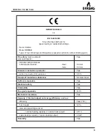
Page 72: ...72 ECO 60 70 90 100 12 DIMENSIONS 12 1 ECO 60...

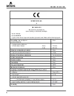
Page 73: ...73 ECO 60 70 90 100 12 2 ECO 70...

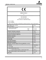
Page 74: ...74 ECO 60 70 90 100 12 3 ECO 90...

Page 75: ...75 ECO 60 70 90 100 12 4 ECO 100 SOAPSTONE...

Page 76: ...mm ext ext ext ext Rear connection 150 mm n a n a n a ext Combustion air supply 125 mm 125 mm 125 mm 125 mm Convection air supply 123 mm 123 mm 123 mm 123 mm connection via the rear ext ext ext ext o...

Page 77: ...O 100 Operation Handle for opening the door Combustion air supply slider Single combined slide for controlling the primary secondary and tertiary air supply Ash collection Ashtray with grate Combustio...

Page 78: ...the ratio of net capacity and gross capacity How can I keep the glass clean By making a point of using dry clean wood in the stove Wood that is too damp immediately gives off lots of ash Make sure the...

Page 79: ...e means that soapstone heats up more quickly than other sorts of stone and emits heat more gradually than other stone Soapstone equalise the irregularity that is a characteristic of burning wood heat...

Page 80: ...ith a closed door and with the combustion air supply slider in the centre position between and In this position the primary air supply beneath the grate is closed and the secondary tertiary air supply...

Page 81: ...ee of moisture is achieved after 1 5 2 years of drying The moisture content is then 15 17 Decomposition At moderate high temperatures 150 C 350 C the decomposition process can be discerned This is whe...

Page 82: ...82 ECO 60 70 90 100...

Page 83: ......

Page 84: ...01 150411 329559 INTERFOCOS B V HALLENSTRAAT 17 5531 AB BLADEL NEDERLAND E mail info barbas nl Internet www barbas com...

Reviews: