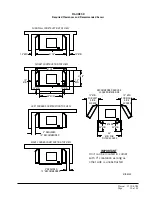
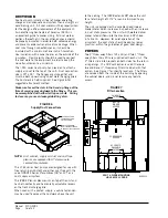
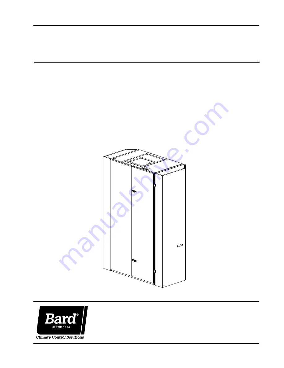
background image

I-TEC SERIES 

PACKAGED HEAT PUMP

Models:

INSTALLATION INSTRUCTIONS

Bard Manufacturing Company, Inc. 
Bryan, Ohio 43506
www.bardhvac.com

Manual: 2100-578L
Supersedes:   2100-578K 
Date: 

 1-31-19

I36Z1-A
I36Z1-B
I36Z1-C

I48Z1-A
I48Z1-B
I48Z1-C

I60Z1-A
I60Z1-B
I60Z1-C

Page 

1 of 42

MIS-3116

Summary of Contents for I-TEC Series

Page 1: ...s INSTALLATION INSTRUCTIONS Bard Manufacturing Company Inc Bryan Ohio 43506 www bardhvac com Manual 2100 578L Supersedes 2100 578K Date 1 31 19 I36Z1 A I36Z1 B I36Z1 C I48Z1 A I48Z1 B I48Z1 C I60Z1 A...

Page 2: ...11 Figure 3 Compressor Shipping Bolts 12 Figure 4 Removal of Air Duct 12 Figure 5A Ducted Application 13 Figure 5B 3 Riser Application 13 Figure 5C 6 Riser Application 14 Figure 5D Required Clearance...

Page 3: ...mmer Manual N Air Conditioning Low Pressure Low Velocity ACCA Manual D or Duct System Design Manual Q Winter and Summer Air Conditioning For more information contact these publishers ACCA Air Conditio...

Page 4: ...ulation made according to methods of Air Conditioning Contractors of America ACCA The air duct should be installed in accordance with the Standards of the National Fire Protection Systems of Other Tha...

Page 5: ...ATMENT X Std Hydrophilic Fin Evap Uncoated Alum Cond Coil 1 Phenolic Coated ID Coil 2 Phenolic Coated OD Coil 3 Phenolic Coated ID OD Coil CONTROLS X 24V Terminal Block Only w o CompleteStat 1 Complet...

Page 6: ...rnal Fuse or Ckt Breaker Field Power Wire Size Ground Wire Size Ckt A Ckt B Ckt A Ckt B Ckt A Ckt B Ckt A Ckt B I36Z1 A0Z A05 A10 j A15 230 208 1 1 1 1 or 2 1 or 2 26 52 78 84 40 60 80 90 8 6 4 4 10 1...

Page 7: ...l 2 2 x24 x30 Front Forklift Holes Remove Front Trim 58 16 94 Entrance High Voltage Entrance Low Voltage 20 x 24 Supply Frame Total Depth 3 8 8 7 With Sides Removed 26 2 4 4 1 2 31 1 61 Total Width 3...

Page 8: ...ceipt of equipment the unit should be checked for external signs of shipping damage The skid must remain attached until the unit is ready for installation If damage is found the receiving party must c...

Page 9: ...of top section and bottom base 4 On each side of the unit is a tie plate that secures the top and bottom sections with four 4 cap bolts Using a wrench or socket remove these screws from both plates an...

Page 10: ...lter access must be considered before installing See Figure 5D for required clearances and recommended service access dimensions SECURING UNIT TO STRUCTURE Shipped with the I TEC unit is a wall mounti...

Page 11: ...View 36 88 20 88 30 06 41 75 56 50 6 00 MIS 3197 A appropriate dimension to height Height dimension shown without 8 00 riser kit If unit uses riser kit add holes 4 lower fastener Inner wall Unit Floor...

Page 12: ...Manual 2100 578L Page 12 of 42 FIGURE 3 Compressor Shipping Bolts FIGURE 4 Removal of Air Duct COMPRESSOR SHIPPING BOLT COMPRESSOR SHIPPING BOLT CRV AIR DUCT...

Page 13: ...TTOM OF ROOF FLOOR OR FIXED CEILING SUSPENDED CEILING 20 MINIMUM 7 9 3 4 UNIT HEIGHT 9 7 MINIMUM CLEARANCE RECOMMENDED TO BOTTOM OF ROOF OR FIXED CEILING 9 2 MINIMUM REQUIRED INSTALLATION HEIGHT BOTTO...

Page 14: ...EARANCE RECOMMENDED TO BOTTOM OF ROOF OR FIXED CEILING 6 RISER FIELD SUPPLIED DUCT MIS 3200 TURNING VANES RECOMMENDED MINIMUM 12 4 MINIMUM FROM TOP OF UNIT TO DUCT BOTTOM FLOOR OR FIXED CEILING BOTTOM...

Page 15: ...12 MIN FOR LEFT SIDE ACCESS SIDE 12 MIN FOR RIGHT ACCESS WING WALL CONSTRUCTION TOP VIEW RIGHT CORNER CONSTRUCTION TOP VIEW LEFT CORNER CONSTRUCTION TOP VIEW CLOSET CONSTRUCTION TOP VIEW FILTERS RECO...

Page 16: ...heat pumps are designed for use with free return non ducted and either duct free with the use of IPBDFZ Series Plenum Box 18 or 12 or a duct supply air system The IPBDZ Plenum Box mounts on top of th...

Page 17: ...ht hand or left hand optional drain locations on the rear of the unit The hole is covered by insulation on the inside of the unit and will have to be cut away Located inside the unit about 12 in from...

Page 18: ...Long Use 12 3 4 Long to Attach Inner Sleeve to Unit Back Self Tapping Screws Use 4 1 2 Long Screws to Attach frame to Exhaust Sleeve Use 12 Field Supplied Concrete or Wood Screws to Secure Outer Slee...

Page 19: ...ed insulated 1 Outside wall 2 Area between sleeve and wall 3 Drain area behind unit SIZE VARIES OUTDOOR GRILLE INSIDE WALL AND SLEEVE INTERIOR FLOOR AREA BETWEEN WALL OUTSIDE WALL INSULATED INSULATED...

Page 20: ...be two field power circuits required If this is the case the unit serial plate will so indicate All models are suitable only for connection with copper wire Each unit and or wiring diagram will be mar...

Page 21: ...stage electric heat When W3 terminal is energized it locks out compressor operation to limit discharge air temperature and required branch circuit ampacity NOTE For total and proper control using DDC...

Page 22: ...el CS9B THO or Model CS9BE THO SC SC GND Thermostat W1 E A YO D L O B Y2 Y1 R G C W2 Bard 8403 060 Blue Yellow Orange 8403 084 MIS 3203 B 1 Not needed below 15KW Factory installed jumper Remove jumper...

Page 23: ...6 1 Not needed below 15KW 2 to N C fire alarm circuit if emergency shutdown required Factory installed jumper Remove jumper and connect Install a jumper between G and A only when thermostat 2 5 Relay...

Page 24: ...move jumper and connect 17 Connect to G terminal when thermostat has Occupancy Signal 3 3 4 CRV Wiring Harness 1 BROWN WHITE ORANGE BLACK WHITE RED WHITE 4 W3 A D C B W1 L 2 RT G Y1 3 Term Strip R 6 I...

Page 25: ...ing multiple leaks and recharges R 410A refrigerant is close to being an azeotropic blend it behaves like a pure compound or single component refrigerant The remaining refrigerant charge in the system...

Page 26: ...er in such a way as to cause rotation in the reverse direction verification of proper rotation must be made Verification of proper rotation direction is made by observing that suction pressure drops a...

Page 27: ...r Heat pump heating cycle now in operation The second option has no Auto changeover position but instead energizes the reversing valve solenoid constantly whenever the system switch on subbase is plac...

Page 28: ...SPEEDUP terminals to accelerate the HPC timer and initiate defrost Be careful not to touch any other terminals with the instrument used to short the SPEEDUP terminals It may take up to 15 seconds wit...

Page 29: ...o cooling load Thus the air conditioner is not running enough to remove the excess moisture being brought in Use a control system that in some way can control the system based upon occupancy RECOMMEND...

Page 30: ...OFF position to eliminate risk of injury or death due to electrical shock 3 Remove six 6 screws holding front CRV door in place See Figure 16 FIGURE 15 CRV Motor Speed CFM Configuration MED HI 7961 7...

Page 31: ...RV Speed Change Terminal Access BLOWER SPEED CONTROL LOCATION BLOWER SPEED CONTROL BLOWER REMOVED FOR CLARITY CRV DOOR TO ACCESS CRV COMPONENTS REMOVE 9 SCREWS FROM MIS 3207 A CRV INTAKE BLOWER NOTE C...

Page 32: ...Manual 2100 578L Page 32 of 42 FIGURE 17 Ventilation Airflow Diagram Indoor Air VENT EXHAUST Supply Air Outdoor Air BLOWER BLOWER INTAKE VENT SUPPLY BLOWER Return Air MIS 3208...

Page 33: ...d capacitor Replace capacitor Reversing valve does not energize heating only Heat pump control defective Check for 24V between RV C and B C 1 Check control circuit wiring 2 Replace heat pump control R...

Page 34: ...31 18 154529 20 46200 58 16122 96 6383 17 149355 21 44855 59 15710 97 6239 16 144374 22 43554 60 15310 98 6098 15 139576 23 42295 61 14921 99 5961 14 134956 24 41077 62 14544 100 5827 13 130506 25 398...

Page 35: ...E 20 Outdoor Condensate Control FIGURE 18 Indoor Condensate Overflow Switch FIGURE 19 Outdoor Condensate Sensor happens on the same cooling call cycle a hard lockout of the compressor circuit will occ...

Page 36: ...d or does not shut off refer to the next section for voltage checks to determine if the motor is getting the proper input signals If the motor IS NOT receiving any communication troubleshoot the commu...

Page 37: ...tion simultaneous to call for compressor operation and is normal RED STATUS LIGHT LA Is illuminated when low ambient control switch is in the closed position NOTE This is not required in heat pump ope...

Page 38: ...ine if it s air noise cabinet duct or motor noise interview customer if necessary Air noise High static creating high blower speed Is airflow set properly Does removing filter cause blower to slow dow...

Page 39: ...hat the replacement control is correct for your application Refer to the manufacturer s authorized replacement list USING THE WRONG CONTROL WILL RESULT IN IMPROPER OR NO BLOWER OPERATION Orient the co...

Page 40: ...f Elec Heat Heat Pump Full Load w 1st 2nd Bank of Elec Heat Emergency Heat Mode Thermostat 24 VAC Inuput Signals G G Y1 Y2 G Y1 Y2 D G B Y1 G B Y1 Y2 G Y1 Y2 B W1 G Y1 Y2 B W2 W3 G W2 W3 Pin 1 24 VAC...

Page 41: ...th the quantity of refrigerant listed on the serial plate AHRI capacity and efficiency ratings were determined by testing with this refrigerant charge quantity The pressure tables on page 42 show nomi...

Page 42: ...85 54 293 60 301 67 309 74 318 81 326 89 334 97 342 106 349 114 356 122 363 130 370 138 377 I60Z1 70 DB Low Side High Side 38 285 42 289 46 293 50 297 54 301 58 305 63 309 67 313 80 335 94 357 100 365...

Reviews: