background image

Page 

1 of 29

INSTALLATION INSTRUCTIONS

Bard Manufacturing Company, Inc. 
Bryan, Ohio 43506
www.bardhvac.com

Manual No.:  2100-416L
Supersedes: 2100-416K
Date: 6-5-20

QC Series

Chilled Water Unit

Models: 

QC501-A   QC501-K   QC501-L

Summary of Contents for QC Series

Page 1: ...f 29 INSTALLATION INSTRUCTIONS Bard Manufacturing Company Inc Bryan Ohio 43506 www bardhvac com Manual No 2100 416L Supersedes 2100 416K Date 6 5 20 QC Series Chilled Water Unit Models QC501 A QC501 K...

Page 2: ...gure 11B Optional Rear Drain 14 Figure 11C Rear Drain Top View 14 Figure 12 Fresh Air Damper Removal 16 Figure 13 Removal of Q TEC ERV 17 Figure 14 Remove Locking Screws from Wheels 18 Figure 15 Unit...

Page 3: ...Procedures for Ground Source IGSHPA Heat Pump Systems Soil and Rock Classification for the Design IGSHPA of Ground Coupled Heat Pump Systems Ground Source Installation Standards IGSHPA Closed Loop Geo...

Page 4: ...d all local codes These Minimum Circuit Ampacity values are to be used for sizing the field power conductors Refer to the National Electric Code latest revision article 310 for power conductor sizing...

Page 5: ...3 3 7 5 10 14 7 10 6 4 1 36 9 24 6 12 3 4 9 11 3 6 48 1000 11 6 9 1 2 5 30 3 21 9 8 4 1 9 4 4 8 12 6 9 6 3 0 32 2 22 6 9 6 3 3 7 5 10 46 6 10 0 3 3 33 7 23 2 10 5 4 9 11 3 6 42 1200 15 9 11 5 4 4 42...

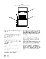
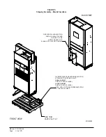
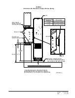
Page 6: ...Manual 2100 416L Page 6 of 29 FIGURE 1 Unit Dimensions...

Page 7: ...LOOR The unit will have to be turned sideways and removed from the skid to fit through a 36 doorway If the door height allows the unit can be slid sideways through the door If the unit cannot be slid...

Page 8: ...unit These instructions and any instructions packaged with any separate equipment required to make up the entire air conditioning system should be carefully read before beginning the installation Not...

Page 9: ...ree blow plenum is 8 6 This provides enough clearance for the plenum to be removed see Figure 7 on page 12 The minimum installation height for ducted applications is 8 4 This provides enough clearance...

Page 10: ...112 289 ATTACHED TO BACK OF UNIT NOTE FOR USE WITH BLANK OFF PLATE OPTION ONLY MIS 4162 NOTE NOT A PICTORIAL REPRESENTATION OF THE ACTUAL SIZES FRONT VIEW Q SERIES SLEEVE MOUNTING BRACKETS 2 ATTACHED...

Page 11: ...WINDOW SILL DIMENSIONS GRILLE CLEARANCE OUTSIDE GRILLE MIS 1614 A THIS DIMENSION MUST REMAIN CONSTANT SPACER FOR WHEN FABRICATING UNIT AND WALL SLEEVE SHOWN WITHOUT SPACER SIZE UNDER UNIT X 2 5 32 750...

Page 12: ...Manual 2100 416L Page 12 of 29 FIGURE 8 Ducted Application FIGURE 7 Installation with Free Blow Plenum CEILING FLOOR FLOOR...

Page 13: ...th the use of QPB Plenum Box or a duct supply air system The QPB Plenum Box mounts on top of the unit and has both vertically and horizontally adjustable louvers on the front discharge grille FIGURE 9...

Page 14: ...e Figure 11A The drain can be routed through the floor or through the wall If the drain is to be routed through an unconditioned space it must be protected from freezing The drain line must be able to...

Page 15: ...turn air grille panel must be opened The fresh air damper assembly can be seen on the back of the unit Refer to Figure 12 on page 16 1 The fresh air damper is attached to the back of the unit with one...

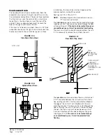
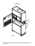
Page 16: ...Manual 2100 416L Page 16 of 29 FIGURE 12 Fresh Air Damper Removal MOUNTING SCREW...

Page 17: ...there is a power connector for the lower blower assembly To FIGURE 13 Removal of the Q TEC Energy Recovery Ventilator FRONT FILL MOUNTING SCREWS LOWER BLOWER ASSEMBLY POWER CONNECTOR POWER CONNECTORS...

Page 18: ...ed lag bolts The fluid piping connections are to be within the confines of this bracket See Figure 1 on page 6 for cabinet openings and location of fluid coil connection points 2 Position the unit in...

Page 19: ...Manual 2100 416L Page 19 of 29 FIGURE 15 Unit Mounting without Ventilation Wall Sleeve SIDE TRIM 2 PIECES SIDE TRIM 2 PIECES WALL MOUNTING BRACKET BOTTOM TRIM EXTENSION BOTTOM TRIM PIECE...

Page 20: ...heat there may be two field power circuits required If this is the case the unit serial plate will so indicate All models are suitable only for connection with copper wire Each unit and or wiring diag...

Page 21: ...um amperage operating condition TABLE 4 Operating Voltage Range TABLE 5 Wall Thermostat Fluid Connections See Figure 1 on page 6 for location of fluid connection Connection size is 1 FPT If the free b...

Page 22: ...l or pin 7 of P2 is the first stage cooling input W1 terminal or pin 8 of P2 is the first stage heating input R terminal or pin 10 of P2 is 24 VAC hot C terminal or pin 11 of P2 is 24 VAC grounded Y2...

Page 23: ...Manual 2100 416L Page 23 of 29 FIGURE 18 Remote Thermostat Wiring Diagram X Option...

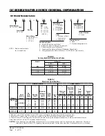
Page 24: ...Manual 2100 416L Page 24 of 29 FIGURE 19 Remote Thermostat Wiring Diagram D Thermostat Option...

Page 25: ...tant Installer Note For improved start up performance wash the indoor coil with dishwashing detergent Service Hints 1 Caution user to maintain clean air filters at all times and to not close off suppl...

Page 26: ...ne if it s air noise cabinet duct or motor noise interview customer if necessary Air noise High static creating high blower speed Is airflow set properly Does removing filter cause blower to slow down...

Page 27: ...eplacement list USING THE WRONG CONTROL WILL RESULT IN IMPROPER OR NO BLOWER OPERATION Orient the control module so that the 3 wire motor plug can be inserted into the socket in the control Carefully...

Page 28: ...Manual 2100 416L Page 28 of 29 FIGURE 23 Internal 2 Way Valve Piping NO side of valve NC side of valve COM side of valve Valve Detail MIS 1899 A Valve Location Water Valves WATER OUT WATER IN...

Page 29: ...Manual 2100 416L Page 29 of 29 FIGURE 24 Internal 3 Way Valve Piping NC side of valve COM side of valve NO side of valve Valve Detail MIS 1900 A Valve Location WATER OUT Water Valves WATER IN...

Reviews: