background image

Type DB5900E

Dri-Bath Test Tube Incubator

Operation Manual

and Parts List

Series 801

Model #

Series

Voltage

DB5915E

801

120

DB5925E

801

120

DB5910E

801

220-240

DB5920E

801

220-240

B

ARNSTEAD

|T

HERMOLYNE

LT801X1 •  3/3/00

Summary of Contents for 801 Series

Page 1: ...5900E Dri Bath Test Tube Incubator Operation Manual and Parts List Series 801 Model Series Voltage DB5915E 801 120 DB5925E 801 120 DB5910E 801 220 240 DB5920E 801 220 240 BARNSTEAD THERMOLYNE LT801X1...

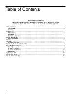
Page 2: ...gnals 3 Warnings 3 Introduction 4 Intended Use 4 Installation 4 Principles of Operation 4 General Specifications 5 Electrical Ratings 5 Operation 6 Calibration 7 Equipment Required 7 Operational Preca...

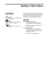
Page 3: ...cor rect voltage and current handling capacity 2 Disconnect from the power supply prior to main tenance and servicing To avoid personal injury 1 Do not use in the presence of flammable or combustible...

Page 4: ...tion Remove the incubator from the carton Check the specifi cation plate on the bottom cover plate for proper voltage and plug into a properly grounded receptacle Principles of Operation The Type DB59...

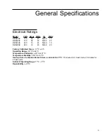
Page 5: ...19 45 50 60 20 Factory Calibrated Temp 37 C 25 Operating Range 30 C to 60 C Temperature Uniformity 20 C at 37 C Temperature Stability 30 C at 37 C Heat up time of unloaded dri bath from a cold start...

Page 6: ...Calibration section for additional instructions You are ready to incubate when the thermometer temperature has stabilized within 1 2 C from the set temperature This dri bath may be calibrated to main...

Page 7: ...test tube 2 Turn the potentiometer on the back of the unit clockwise as you look at the back of the unit to increase temperature and counterclockwise to decrease temperature The potentiometer rotates...

Page 8: ...e well depth 3 Placing a full load of cold tubes in the dri bath will extend the recovery time 4 Only 13 mm test tubes should be used in the dri bath to obtain optimum results 8 Operational Precaution...

Page 9: ...ews and washers which are located on the aluminum plate These screws hold the heating element onto the casting they also hold the block to the casting 7 Remove the plate with the PC board and lay it t...

Page 10: ...Carefully remove thermistor from block 6 Remove PC board from clips 7 Install new PC board Reconnect line cord leads terminals marked L1 L2 white or blue on L2 black or brown on L1 Reconnect element...

Page 11: ...Defective Control Board Replace Board Open Element Replace Element Loose or Broken Connection Reconnect or replace faulty connection Unit heats full on Potentiometer set at maximum Check Potentiomete...

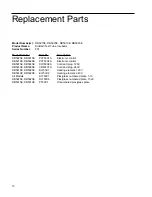
Page 12: ...DB5920E PC753X2A Electronic control DB5915E DB5925E CR760X2A Cord and plug 120V DB5910E DB5920E CR801X1A Cord and plug 240V DB5915E DB5925E EL753X1 Heating element 120V DB5910E DB5920E EL753X2 Heating...

Page 13: ...m whom you purchased this unit or can be obtained promptly from the factory When service or replacement parts are needed we ask that you check first with your dealer If the dealer cannot handle your r...

Page 14: ...own discretion Heating elements however because of their susceptibility to overheating and contamination must be returned to our factory and if upon inspection it is concluded that failure is not due...

Page 15: ...15...

Page 16: ......

Reviews: