background image

Riding Sweeper

Service Manual

Serial No. FS900

10001-


Ver.1.0

Summary of Contents for FS900

Page 1: ...Riding Sweeper Service Manual Serial No FS900 10001 Ver 1 0...

Page 2: ...ine Baroness parts or parts designated by Kyoeisha Note that the Baroness product warranty may not apply to defects caused by the use of parts from other companies Warning Symbols This manual uses the...

Page 3: ...easurement Page 5 5 Adjustment Page 5 7 Electrical components Page 5 8 General inspection and repair Page 5 18 Main body Page 6 1 Maintenance Page 6 2 Specifications Page 6 2 Special Tool Page 6 3 Adj...

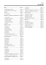
Page 4: ...FS900 Contents...

Page 5: ...Page 1 2 Training Page 1 2 Preparation Page 1 2 Operation Page 1 3 Maintenance and storage Page 1 4 Safety Signs and Instruction Signs Page 1 5 About Safety Signs and Instruction Signs Page 1 5 Safet...

Page 6: ...its task Lack of awareness of the effect of ground conditions especially slopes 1 2 3 1 2 Incorrect hitching and load distribution Never allow children or people unfamiliar with these instructions to...

Page 7: ...s or without safety protective devices in place Be sure all interlocks are attached adjusted and functioning properly 5 5 6 7 1 2 3 4 1 2 3 4 5 6 5 Do not change the engine governor settings or oversp...

Page 8: ...off valve shut off valve while storing or transporting Do not store fuel near flames 17 18 19 20 21 1 2 3 4 5 6 7 8 Never allow untrained personnel to service machine Allow the engine muffler to cool...

Page 9: ...ction Signs Warning Safety decals and instruction decals are attached to this machine Make sure that they are preserved in their entirety If they are damaged become dirty or peel off replace them with...

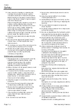
Page 10: ...FS900 Safety Page 1 6 Safety Signs and Instruction Signs...

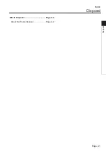
Page 11: ...Waste Disposal Page 2 2 About the Waste disposal Page 2 2 Disposal FS900 Disposal Page 2 1...

Page 12: ...sposal Make sure that waste generated when servicing or repairing the machine is disposed of in accordance with local regulations e g waste oil antifreeze batteries rubber products and wires etc FS900...

Page 13: ...torques Page 3 5 Standard tightening torques Page 3 5 Principal tightening torques Page 3 8 General precautions Page 3 9 Bearing Page 3 9 Stop ring Page 3 10 Jacking up the machine Page 3 11 About th...

Page 14: ...9 7 32 0 21875 5 556 23 32 0 71875 18 256 15 64 0 234375 5 953 47 64 0 734375 18 653 1 4 0 2500 6 350 3 4 0 7500 19 050 17 64 0 265625 6 747 49 64 0 765625 19 447 9 32 0 28125 7 144 25 32 0 78125 19 8...

Page 15: ...bic Meters Cubic Centimeters m3 m3 cm3 0 7646 0 02832 16 39 Weight Tons Short Pounds Ounces Avdp sh tn lb oz Metric Tons Kilograms Grams ton kg g 0 9078 0 4536 28 3495 Pressure Pounds Sq In Pounds Sq...

Page 16: ...m 0 669 in Pump drive belt tension Adjust the belt tension so that the spring cover is not lifted H PXSB43 Brush belt tension Approx 10 mm sag under the finger pressure 98 N or 10 kgf on the V belt in...

Page 17: ...efore sufficient tightening cannot be applied If screw is wet by water or oil do not tighten it with normal tightening torque If the screw is wet the torque coefficient will get smaller and it may res...

Page 18: ...75 593 02 752 34 104 134 1 060 49 1 366 40 920 50 1186 03 M14 106 134 1 080 88 1 366 40 938 21 1 186 03 140 188 1 427 58 1 917 04 1 239 14 1 663 99 M16 152 188 1 549 94 1 917 04 1 345 35 1 663 99 210...

Page 19: ...3 4 117 68 1200 1 355 78 19 3 4 117 68 1200 1 355 78 25 1 137 30 1400 1 581 74 32 1 1 4 166 72 1700 1 920 69 38 1 1 2 205 94 2100 2 372 61 50 2 245 17 2500 2 824 54 Fittings with parallel threads O r...

Page 20: ...t treated M12 25P1 5 67 85 683 20 833 75 593 02 752 34 Wheel K0010100302 Bolt heat treated M10 30 45 76 458 87 774 97 398 30 672 68 Rea r whe el Wheel mounting seat K0160000492 Special nut M24 P1 5 18...

Page 21: ...g using the bearing driver 3 2 1 gr5d95 001 Bearing_001 1 Shaft 2 Bearing 3 Bearing driver When pressing the bearing into the housing apply pressure evenly around the outer ring of the bearing using t...

Page 22: ...top rings one for a hole and one for a shaft Both stop rings have a front and a back The front side is rounded and the back side has a sharp edge 1 2 4b82yb 001 Stop Ring_001 1 Stop ring for hole 2 St...

Page 23: ...move or fall resulting in injury or death Use the jack up points identified in this manual when jacking up the machine Only place a jack under the jack up points specified Placing a jack at any other...

Page 24: ...Left rear frame area rwyt62 030 Jack up Points_005 4 FS900 Maintenance standards and maintenance Page 3 12 Jacking up the machine...

Page 25: ...easing Points 1 Traveling pedal fulcrum 1 2 Brush frame fulcrum 2 3 Flange bearing 1 4 Upper connecting pipe 2 5 Upper adjusting pipe 2 6 Belt tension lever fulcrum lower pulley for pump 1 7 Brake ped...

Page 26: ...ipe There is one point each on the left and right 8bq62b 083 Greasing Points_006 3 4 5 Belt tension lever fulcrum lower pulley for pump 8bq62b 084 Greasing Points_007 Brake pedal fulcrum 8bq62b 085 Gr...

Page 27: ...Lower connecting pipe There is one point each on the left and right 8bq62b 089 Greasing Points_012 9 10 11 Rear roller There is one point each on the left and right 8bq62b 090 Greasing Points_013 Fron...

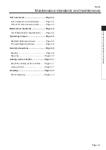
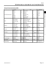
Page 28: ...FS900 Maintenance standards and maintenance Page 3 16 Greasing...

Page 29: ...t failure Page 4 16 Hydraulic circuit flow Page 4 17 Traveling circuit Page 4 17 Work machine circuit Page 4 19 Special Tool Page 4 24 List of Special Tools Page 4 24 Measurement Page 4 28 Note Page 4...

Page 30: ...r s Operating Manual and Parts Catalog To maintain the integrity of the hydraulic device you must not overhaul the device for maintenance For those parts that must be repaired by the manufacturer the...

Page 31: ...lacement 158 cm3 rev 9 64 in3 rev Orbit motor J 20EBD Displacement 19 8 cm3 rev 1 21 in3 rev Stack valve EATON SV3 4228 Relief set pressure 13 7 MPa 140 kgf cm2 1986 94 psi Flow 18 L min 4 75 U S gals...

Page 32: ...385 66 5 23 1 83 2 1 26 21 2 1 83 2 dwb7jb 011 Hydraulic System Layout_001 1 Piston pump 4 Orbit motor 7 Stack valve 2 Up down cylinder 5 FPV1 series valve 8 Suction filter 3 Wheel motor 6 Line filter...

Page 33: ...ated on the right side of the brush frame FPV1 series valve This is a valve for applying pressure to the operating machine The valve switches direction by a lever system This is located on the right s...

Page 34: ...S1 P2 B2 S2 zy6f9z 006 Flow of Oil during Forward Traveling_001 shows flow of oil The flow of oil shows that for forward traveling shows port name 1 Piston pump 3 Wheel motor left 5 Suction filter 2...

Page 35: ...g Rolling and Brush Rotation_001 shows the flow of oil This oil flow occurs when the brush frame is lowered rolling is performed and the brush is rotated shows port name inside 1 Piston pump 4 Orbit m...

Page 36: ...Bucket and Opening Bucket Lid_001 shows the flow of oil This oil flow occurs when the bucket is raised and the bucket lid is opened shows the port name inside 1 Piston pump 4 Cylinder bucket up down 7...

Page 37: ...anner vuy27z 001 Hydraulic hose_001 Warning Be sure to depressurize the hydraulic system before maintaining or repairing it Stop the engine and lower the rake When checking for pinhole leakage of the...

Page 38: ...be rotated by hand This point is called the zero point w7s31b 006 Bite type tube fitting_006 4 5 Matchmark the zero point and further tightening of 3 4 to one turn will cause the sleeve to bite into...

Page 39: ...the fitting body to follow procedures 1 to 5 when using a temporary tightening tool and set the zero point Further tighten for 1 and 1 4 turn from the zero point w7s31b 010 Bite type tube fitting_010...

Page 40: ...then tighten securely with a tool such as a spanner Adjustable Elbow jf65lf 001 Adjustable Elbow_001 1 2 3 4 Make sure that the positions of the nut washer and O ring are correct If they are in the c...

Page 41: ...kage Rough installation makes the main body and nut overloaded which leads to deformation Be sure to observe the installation procedure To fit screw the main body by hand till the washer face touches...

Page 42: ...nnecting the joint wind sealing tape on the taper thread portion See How to Use the Sealing Tape Page 4 14 1 14d3iz 003 Taper Pipe PT Thread Joint Sealing Tape Method _003 1 Taper PT thread portion Ho...

Page 43: ...002 1 Sealing area 2 Sealing tape 3 Clockwise direction Wrap it in clockwise direction direction to tighten the screw about 1 5 to 2 turns from edge to root starting from the point of 1 to 2 threads a...

Page 44: ...king brake and then lower the operating machine Then stop the engine and remove the key To depressurize the hydraulic circuit set the traveling pedal and all the drives of the operating machine to the...

Page 45: ...ntake return Direction Piston pump R1 Relief pressure 20 6MPa R2 Relief pressure 1 0MPa 3 3 3 5 5 7 6 6 Wheel motor Wheel motor DUWULGJH ILOWHU 10 m Suction filter To Valve Multiple FRV1 g5t8is 026E F...

Page 46: ...ure Low pressure charge Intake return Direction Piston pump R1 Relief pressure 20 6MPa R2 Relief pressure 1 0MPa Wheel motor Wheel motor To Valve Multiple FRV1 Suction filter 7edlvx 029E Backward trav...

Page 47: ...Intake return Direction Brush rotation motor Bucket up down Lid open close Stack valve R4 Relief valve 13 7MPa Brush frame up down Surface compaction 7 3 5 PLQ 7 1 3 5fl96a 001E Raising the Brush Fram...

Page 48: ...take return Direction Brush rotation motor Bucket up down Lid open close Stack valve R4 Relief valve 13 7MPa Brush frame up down Surface compaction 7 3 5 PLQ 7 1 3 22c3vd 001E Lowering the Brush Frame...

Page 49: ...ation motor Bucket up down Lid open close Stack valve R4 Relief valve 13 7MPa Brush frame up down Surface compaction 5 7 3 5 PLQ 7 1 Valve Multiple FRV1 Relief valveR3 0 9MPa 3 iiy3gr 001E Lowering th...

Page 50: ...take return Direction Brush rotation motor Bucket up down Lid open close Stack valve R4 Relief valve 13 7MPa Brush frame up down Surface compaction 7 3 5 PLQ 7 1 3 5bjwpw 001E Raising the Bucket and O...

Page 51: ...urn Direction Brush rotation motor Bucket up down Lid open close Stack valve R4 Relief valve 13 7MPa Brush frame up down Surface compaction 7 3 5 PLQ 7 1 3 7cu6iu 001E Lowering the Bucket and Closing...

Page 52: ...re measurements vasdfi 004 K4701000020 Pressure For the range of 0 15 MPa For the range of 0 2 175 60 psi For the range of 0 152 96 kgf cm2 Primarily used for measuring the pressure of low pressure pa...

Page 53: ...shut off the fluid to be measured during maintenance inspection or repair etc of the pressure gauge Pressure gauge joint vasdfi 006 K4701000040 Used as a joint for pressure pipes Female connector 1015...

Page 54: ...042 Y Used as an adapter for the T joint during pressure measurements Adapter 1013 9 q9c6v6 008 K3000090002 Y Used as an adapter for the T joint during pressure measurements quantity used two WP280 6...

Page 55: ...a hydraulic hose for extremely low pressure measurements Adapter 1013 6 q9c6v6 047 K3000060002 Y Used as a connector when installing the pressure gauge to the pressure measuring port Hydraulic system...

Page 56: ...nt Remember that the machine must always be kept clean for pressure measurement Contamination may lead to clogging or breakage of the hydraulic circuit 1 Review the measuring method before starting me...

Page 57: ...pressure charge Intake return Direction Piston pump R1 Relief pressure 20 6MPa R2 Relief pressure 1 0MPa Wheel motor Wheel motor To Valve Multiple FRV1 Cartridge filter 10 m Suction filter g5t8is 027E...

Page 58: ...s 3 2 1 4 g5t8is 028 Forward_002 1 Forward side measuring port elbow 2 Screw cap 3 Brush frame 4 Pressure gauge for high pressure measurements Secure the pressure gauge for high pressure measurements...

Page 59: ...ure 2 1 g5t8is 031 Forward_005 1 Sling 2 Bottom position of bucket Use a sling etc to apply resistance so that the machine does not advance forward Start the engine and rev it up to the maximum rpm Pr...

Page 60: ...uge High pressure Low pressure charge Intake return Direction Piston pump R1 Relief pressure 20 6MPa R2 Relief pressure 1 0MPa Wheel motor Wheel motor Suction filter To Valve Multiple FRV1 7edlvx 030E...

Page 61: ...ressure gauge for high pressure measurements Attach the pressure gauge for high pressure measurements 1 2 3 Secure the pressure gauge for high pressure measurements with a band or the like 2 1 g5t8is...

Page 62: ...ke return Direction Brush rotation motor Bucket up down Lid open close Stack valve R4 Relief valve 13 7MPa Brush frame up down Surface compaction Pressure gauge 7 3 5 PLQ 7 1 3 z4kw7w 038E Up Down Cir...

Page 63: ...h pressure measurements 1 2 3 Important The G port plug is a PT screw When installing the plug wrap the thread area with seal tape and tighten the plug using the appropriate torque Install the adapter...

Page 64: ...ush rotation motor Bucket up down Lid open close Stack valve R4 Relief valve 13 7MPa Brush frame up down Surface compaction Valve Multiple FRV1 Relief valveR3 0 9MPa 7 3 5 5 PLQ 7 1 3 Pressure gauge i...

Page 65: ...ly low pressure measurements to the special T PT1 4 PF1 4 1 2 3 4 Secure the pressure gauge for extremely low pressure measurements to the main frame using bands Note Route the hydraulic hose in posit...

Page 66: ...irection Piston pump R1 Relief pressure 20 6MPa R2 Relief pressure 1 0MPa 3 3 3 5 5 7 6 6 Wheel motor Wheel motor To Valve Multiple FRV1 Cartridge filter 10 m Suction filter Pressure gauge zg85f8 032E...

Page 67: ...asurements 2 Adapter 3 Threaded tee 4 Special adapter 5 Hydraulic hose 6 Connecting location of the elbow from which the hose was removed 7 Connecting location of the removed hydraulic hose 1 2 Instal...

Page 68: ...hydraulic oil leakage in each part See the list in Tightening torques Page 3 5 Note that the Baroness product warranty may not apply to defects caused by incorrect or overtorque tightening etc Check...

Page 69: ...draulic system before inspecting or repairing it Important Be sure to clean the circuit connecting part to be repaired Drain the oil from the hydraulic tank 1 2 3 4 5 Drain the oil from the hydraulic...

Page 70: ...the hydraulic circuit is filled with oil operate the up down lever and switches to operate the up down cylinder several times Stop the engine immediately when the cylinder does not move within 10 to...

Page 71: ...hzyz 001 Hydraulic Oil Supply_001 1 Knobs 2 Front cover 1 2 3 1 Remove the bolts and then open the cover 2 1 dmhzyz 002 Hydraulic Oil Supply_002 1 Bolt 2 Cover If the oil level is low open the tank ca...

Page 72: ...and then pour new oil from the fill port until the oil level reaches the middle of the oil gauge on the hydraulic tank The hydraulic tank capacity is approximately 17 0 dm3 17 0 L 1 dmhzyz 003 Hydraul...

Page 73: ...malfunction of the hydraulic system Replace the hydraulic oil filter periodically Timing of replacing The first time After 100 hours of operation The second time or after Every 500 hours of operation...

Page 74: ...FS900 Hydraulic system Page 4 46 Inspection and repair of each section...

Page 75: ...rd reverse pedal proximity switch Page 5 7 Electrical components Page 5 8 About the Electrical components Page 5 8 Traveling Pedal Proximity Switch Page 5 10 Forward reverse pedal proximity switch NC...

Page 76: ...r the FS900 electrical system For information on daily checks maintenance and handling of the machine please refer to the separate FS900 Owner s Operating Manual and Parts Catalog For details on handl...

Page 77: ...art Layout_001 1 Brake pedal switch 6 Key switch 11 Seat switch NC type push to turn off 2 Power relay CA1 DC12V N 7 Warning buzzer switch 12 Sensor 3 Power relay MR5A602A1K 8 Hour meter 13 Magnetic s...

Page 78: ...eck and maintenance schedule is based on the number of hours indicated on this meter It is located in the lower right area of the operation panel Traveling pedal proximity switch NC The traveling peda...

Page 79: ...of 12V battery Check all the cells after charge Replace the battery when the specific weight is 1 225 or less or gap of that between each cell is 0 05 or more 1 lyp58z 001 Measurement of Battery Spec...

Page 80: ...essed The engine will stop under any of the following conditions The parking brake is applied the operating leaves the seat the traveling pedal forward reverse pedal is pressed The parking brake is re...

Page 81: ...79 in or more B 6 mm 0 24 in or less Forward reverse pedal proximity switch Adjust the position of the forward reverse pedal proximity switch so that gap A is 5 mm 0 20 in or less when the forward and...

Page 82: ...ure to disconnect the negative battery cable Safety Switches The following devices are used as safety switches to prevent injuries and accidents due to operator inattentiveness Seat switch Parking bra...

Page 83: ...9 BW 20 Y 14 BW 26 YR 26 YR 30 YR 6 RW 33 B 25 B 18 B 32 Br 15 Br 21 YR 31 RB 29 RW 4 BW 17 WR 27 Y BY 5 YW B 1 R 2 B 2 B 1 28 B 5 BY 3 RL 24 R R 2 27 Y 3 6 RW 4 7 YR BAT 8 7 6 5 3 2 9 4 1 1j8hum 001...

Page 84: ...s activated and the starter motor circuit is shut off and the start motor does not run When the operator is not sitting in the seat the seat switch signal activates relay number 8 602 the starter moto...

Page 85: ...tester to the connector terminal Vout and the tester to the connector terminal Normal operation is that there is continuity between connector terminals 2 and 3 when the plastic magnet is getting away...

Page 86: ...normal that the voltage between connector terminals 2 and 3 is the battery voltage 12 V when the plastic magnet is getting away to the proximity switch and that voltage drops to 0 V when the plastic...

Page 87: ...17kq1q 002 Buzzer Switch_002 1 2 3 Power Relay Power Relay 602 Interlock System Power Relay The power relay MR5A602A1K gray is one part that makes up the interlock system and is controlled by activati...

Page 88: ...n of Power Relay_002 Caution Do not short circuit the battery terminals Normal operation is when there is no continuity between 3 and 6 and there is continuity between relay terminals 4 and 5 with the...

Page 89: ...Caution Do not short circuit the battery terminals Normal operation is when there is no conduction between between relay terminals 3 and 5 with the battery connected to relay terminals 1 and 2 2 5 4 3...

Page 90: ...ur meter_001 1 1 10 wheel 2 Hour wheel Fuses Warning When performing maintenance on the electrical system be sure to remove the negative battery wire Caution If a fuse blows a short may have occurred...

Page 91: ...of the figure a large current flows to the starter motor from the battery the starter motor starts to turn and the engine starts When the key switch is set to the ON position the magnetic force in th...

Page 92: ...e contained in the battery is sulfuric acid Contact of the electrolyte sulfuric acid with the skin could cause blindness or burns Contact of the electrolyte with the machine etc could cause damage to...

Page 93: ...ause damage to the instruments When cleaning the battery do not use organic solvents such as benzene thinner or gasoline and refrain from using cleaner or chemical cloth Doing so could damage the batt...

Page 94: ...U P P E R L E V E L L O W E R L E V E L 1 2 48yhlu 006 Inspection of the battery_001 4 5 1 Upper limit 2 Lower limit Replacement of Battery When replacing the battery note the following precautions an...

Page 95: ...nections or electrolyte leaks from around the terminals Replace the battery with one that is the same size When replacing the battery follow these steps Removing the old battery Important Be careful w...

Page 96: ...of the battery respectively If they are connected reversely or loosely it may cause ignition explosion failure of the battery charger or damage on the vehicle or equipment due to the polarity inversio...

Page 97: ...rging to recover the battery left for a long time A high electrolyte temperature deteriorates parts such as polar plates inside the battery and shorten its lifetime Electrical system FS900 Electrical...

Page 98: ...FS900 Electrical system Page 5 24 General inspection and repair...

Page 99: ...e Page 6 5 Neutral Position of the Piston Pump Page 6 7 Pump Drive Belt Page 6 8 Steering Page 6 9 Removal and installation of each section Page 6 10 Steering Section Page 6 10 Front wheels Section Pa...

Page 100: ...gf cm2 psi Front wheel 80 0 8 11 60 Rear wheel 120 1 2 17 40 Adjusted Value mm in Adjustment of steering angle of steering wheel Distance between steering stopper bolt and frame front surface 17 0 669...

Page 101: ...talling bearings with outer 72 and inner 35 6206 Bearing driver q9c6v6 009 K4802000832 Used when installing bearings with outer 62 and inner 30 6205 Bearing driver q9c6v6 010 K4802000822 Used when ins...

Page 102: ...6305 Bearing driver q9c6v6 010 K4802000832 Used when installing bearings with outer 62 and inner 25 FS900 Main body Page 6 4 Special Tool...

Page 103: ...reased and the brake pedal feel is heavy 2 1 3 nfzln9 007 Adjustment of Brake_001 1 Brake wire 2 Adjustment bolt 3 Brake lever Start the engine and drive to check the following Make sure that heat is...

Page 104: ...by the adjustment bolt 2 1 3 nfzln9 007 Adjustment of Parking Brake_001 1 Brake wire 2 Adjustment bolt 3 Brake lever Follow the steps below to adjust the parking brake Check position of the notch of t...

Page 105: ...aise the machine until the tires lift off the ground See Jack up Points Page 3 11 Start the engine and rev it up to the maximum rpm Slowly rotate the camshaft until the rear wheels stop and then lock...

Page 106: ...e middle of the belt with your finger to check the belt tension Tighten the high nut until there is no clearance between the spring cover and the tension fulcrum fitting and then lock it in place with...

Page 107: ...y that the steering wheel stopper comes into contact with the steering wheel stopper bolt when the steering wheel is turned left or right 1 76ain2 002 Adjusting the Steering Angle of the Steering Whee...

Page 108: ...moving the Steering Wheel Section_001 1 Steering wheel 2 Front cover 3 Relay wire 4 Panel stay 5 Grip section of throttle lever 6 Grip section of tilt lever 7 Warning lamp and buzzer wire 8 Harness 9...

Page 109: ...tach the tilt lever Attach a washer disc spring washer and tilt lever in that order to the frame with the tilt lever bolt Secure the tilt lever bolt with bolts with hexagonal hole and nuts B so that t...

Page 110: ...bearing cover Prepare a temporary bolt that is at least 25 mm longer than the heat treated bolt Insert the long bolt about 15 mm in place of the heat treated bolt Caution Do not quickly lower the jack...

Page 111: ...ring shaft using the hammer in the direction of the arrow and remove the steering shaft 1 3 2 2 4 3 xbg984 001 Inspecting the Axle Installation Bracket_001 1 Axle installation bracket ass y 2 Stop rin...

Page 112: ...5 Bearing outer diameter The shaft washer and the housing washer have different outer diameter and inner diameter dimensions Assemble the parts while checking the secured side The secured side of the...

Page 113: ...8 Temporarily install the tie rod end right ass y 3 1 2 4 5 6 zd6qac 008 Inspecting the Front Wheel Arm_005 1 Front wheel arm 2 Bearing 3 Ball 4 Housing washer 5 Shaft washer 6 Tie rod end right inst...

Page 114: ...6 8 6717fe 002 Inspecting the Front Wheel Arm_006 1 Front wheel arm ass y 2 Jack 3 Heat treated bolt 4 Spring washer 5 Bearing cover 6 Bearing 7 Tie rod end right ass y 8 Housing main body Apply greas...

Page 115: ...ps to remove them from the other side 1 7 6 5 4 3 2 6 cvjrk2 001 Inspecting the Wheel Installation Shaft_001 1 Wheel installation shaft ass y 2 Special heat treated bolt 3 Spring washer 4 Wheel tighte...

Page 116: ...Brake shoe wears out gradually as the brake is used just like an eraser Check the remaining amount at the inspection Replace if it is too small Disassembly and assembly of brake A brake shoe can be r...

Page 117: ...wash off oil with brake cleaner etc Apply grease to the sliding parts when assembling z2sgi8 005 Disassembly and assembly of brake_005 Adjust the clearance of the shoe Turn the adjustment screw to ad...

Page 118: ...FS900 Main body Page 6 20 Inspection and repair of each section...

Page 119: ...of Rotary Plates Page 7 7 Adjusting the Bucket Page 7 8 Adjusting the Bucket Lid Page 7 10 Removal and installation of each section Page 7 11 Bucket Page 7 11 Bucket Mounting Frame Page 7 14 Working U...

Page 120: ...ease on the operating machine and mower units Grease Excelite EP No 2 urea base Adjusted Value Adjustment of brushes Gap between brush and frame 5 mm 0 197 in Adjustment of rotary plates Gap between r...

Page 121: ...gs with outer 55 and inner 30 6005 Bearing driver q9c6v6 010 K4802000502 Used when installing bearings with outer 47 and inner 25 35 Oil seal installer q9c6v6 011 K4802000782 Used when installing 35 o...

Page 122: ...y adjusted the brushes will not rotate properly Move the machine to level ground then apply the parking brake Lower the operating machine Stop the engine Remove the four bolts and then remove the belt...

Page 123: ...ly 001 Adjustment of Brushes_001 1 Bucket up down lever A Up Stop the engine Important To keep the position of raised bucket be sure to lock it with the cylinder lock 1 2 3 Remove the cotter pin and r...

Page 124: ...rotary brushes by hand and then follow the same steps to adjust the remaining brushes and temporarily tighten the bolts Caution Refer to Tightening torques Page 3 5 Note that the Baroness product warr...

Page 125: ...th the cylinder lock Remove the cotter pin and round head pin and then lower the cylinder lock 2 1 3 xsi3tb 001 Adjustment of Rotary Plates_002 1 Cotter pin 2 Round head pin 3 Cylinder lock 1 2 3 4 In...

Page 126: ...y to defects caused by incorrect or overtorque tightening etc Slowly rotate the rotary plates by hand check the clearance again and tighten the bolts After making adjustments and tightening the bolts...

Page 127: ...bucket mounting frame in the direction of the arrow and adjust the clearance to the 10 mm 0 393 in setting value Caution Refer to the Tightening Torque Table Note that the Baroness product warranty m...

Page 128: ...een the bucket and the lid by tightening the adjustment screw so that the gap is 1 mm 0 039 in 1 3 4 5 2 y3iw5c 001 Adjusting the Bucket Lid_001 1 Bucket 2 Lid 3 Upper gap 4 Adjustment screw 5 Lower g...

Page 129: ...2 Removing the Bucket_002 1 Harness clip 2 Bolt 3 Spring washer 4 Nylon band 1 2 3 4 5 6 Remove the bucket lid open close kit from the machine and place the kit as shown in the figure 1 yi8si6 003 Rem...

Page 130: ...ket_007 11 12 13 14 1 Bucket up down cylinder 2 Split pin 3 Pin 4 Washer 5 Bolt 6 Spring washer 7 Washer Caution The bucket is heavy Be sure to use a hoist or a chain block Attach a sling to the bucke...

Page 131: ...rect or overtorque tightening etc Important When installing the bucket arm and adjusting pipe apply grease to moving parts After installation apply additional grease For installation reverse the remov...

Page 132: ...the like and remove the bolt in a position where there is no resistance applied to the bolt Remove the heat treated bolt washers spring washer and nut Follow the same steps to remove them from the ot...

Page 133: ...so there is a little tension 1 2 47n2pv 002 Removing the Operating Section_002 1 2 3 4 5 1 Operating section 2 Sling Remove the split pin flathead pin and washer Remove the up down cylinder from the...

Page 134: ...h frame link pipe 3 Shaft 4 Bolt 5 Spring washer 6 Washer 10 11 12 13 14 Caution Removing the operating section is a two person job Be sure to firmly support the operating section Remove the operating...

Page 135: ...cog belt 1 2 3 4 5 6 7 8 Remove the bolt spring washer washer and double head round key and remove the pulley 1 2 3 4 5 zhswjf 003 Removing the Brush Shaft_003 1 Bolt 2 Spring washer 3 Washer 4 Doubl...

Page 136: ...The brush shaft has a specific installation direction Verify the direction before installation 15 Important When installing the brush shaft apply grease to the input area After installation apply add...

Page 137: ...4 Washer B 5 Disc spring 6 Low edge cog belt 1 2 3 4 5 6 7 8 Remove the bolt spring washer washer and double head round key and remove the rotary pulley 3 4 5 2 1 it27ka 001 Removing the Rotary Shaft_...

Page 138: ...Washer 6 Spring washer 7 Nut 13 Remove the two bolts spring washers and washers from the motor housing and then remove the rotary shaft 1 1 2 3 4 2 3 4 it27ka 004 Removing the Rotary Shaft_006 1 Motor...

Page 139: ...to the input area After installation apply additional grease Important Apply a locking agent to the set screw Important The flange unit has a specific installation direction Verify the direction befo...

Page 140: ...n the direction of the arrow and remove the roller bracket from the boss 1 2 3 4 5 6 7 8 9 10 Danger Danger The operating section may drop Be sure to hold the upper side of the roller While holding th...

Page 141: ...ly the parking brake Shift the bucket up down lever to the UP position to raise the bucket ON OFF OPEN UP CLOSE FREE PURESS DOWN DOWN UP 1 A 5c6vly 001 Change of Brushes_001 1 Bucket up down lever A U...

Page 142: ...tely 5 mm Slowly rotate the rotary brushes by hand and then follow the same steps to adjust the remaining brushes and temporarily tighten the bolts Caution Refer to Tightening torques Page 3 5 Note th...

Page 143: ...LOSE FREE PURESS DOWN DOWN UP 1 A 5c6vly 001 Change of Rotary Plates_001 1 Bucket up down lever A Up Stop the engine 1 2 3 Important To keep the position of raised bucket be sure to lock it with the c...

Page 144: ...A 5 mm Slowly rotate the rotary plates by hand and then follow the same steps to adjust the remaining rotary plates and temporarily tighten the bolts Caution Refer to Tightening torques Page 3 5 Note...

Page 145: ...bearing Remove the rear roller ass y See Removing the Rear Roller Ass y Page 7 22 Remove the left and right nipples Loosen the bolt with a hexagonal hole and remove the nut 1 2 3 y2frzp 001 Inspection...

Page 146: ...o the opposite side Remove the oil seal collar and taper bearing inner 2 1 4 3 5 y2frzp 003 Inspection of Rear Roller_005 1 Roller shaft 2 Roller 3 Taper bearing inner 4 Collar 5 Oil seal Remove the s...

Page 147: ...ng 2 Oil seal Caution Refer to the Tightening Torque Table Note that the Baroness product warranty may not apply to defects caused by incorrect or overtorque tightening etc Install the rear roller ass...

Page 148: ...motor housing See Removing the Rotary Shaft Page 7 19 Remove the stop ring Place the motor housing on a vise or the like tap from the direction indicated by the arrow and remove the oil seal and bear...

Page 149: ...Relating to the Engine Page 8 2 Relating to Traveling Page 8 4 Relating to Steering Page 8 5 Operating Machine Related Page 8 6 Troubleshooting FS900 Troubleshooting Page 8 1...

Page 150: ...the aforementioned causes Starter motor failure Engine Maintenance Manual Loose battery cable Electrical System General Inspections Repairs Battery Engine does not start when it cranks with the start...

Page 151: ...wner s Operating Manual Clogged air cleaner element This machine s Owner s Operating Manual Clogged carburetor Engine Maintenance Manual Engine rpm is slow No charge Loose battery cable Electrical Sys...

Page 152: ...without the aforementioned causes Engine rpm is slow Engine does not run smooth Engine Maintenance Manual The parking brake is applied This machine s Owner s Operating Manual The actuating pump lever...

Page 153: ...Arm Inspecting the Front Wheel Arm Malfunction of axle mounting shaft fulcrum section Main Body Inspection of Each Part Repair Wheel Installation Shaft Inspecting the Wheel Installation Shaft Malfunc...

Page 154: ...Unit Adjustment Adjusting the Brush Belt The brush shaft rotation is slow Adjusting the Cog Belt Operating Machine and Mower Unit Adjustment Adjusting the Brush Belt The bucket does not go up Malfunct...

Page 155: ...cations Page 9 2 Maintenance Schedule Page 9 3 Hydraulic Circuit Diagram Page 9 5 Electrical Circuit Page 9 6 Electric Wiring Diagram Page 9 7 List of Consumables Page 9 8 Reference FS900 Reference Pa...

Page 156: ...pneumatic pressure rubber tires Front wheel 80 kPa 0 8 kgf cm2 11 60 psi Rear wheel 120 kPa 1 2 kgf cm2 17 40 psi Operating machine Operating width Mowing width 81 cm 31 89 in Engine Model Vanguard 3...

Page 157: ...uel Air cleaner Engine oil 8 hrs first time Engine oil filter 50 hrs first time Ignition plug Battery Battery fluid Cleaning the exterior Main body Tightening the parts Interlock system Electrical wir...

Page 158: ...rs Every year Every 2 years Every 4 years Remarks Main body Hydraulic hose moving part Hydraulic hose fixed part Fuel strainer Fuel pipe Cleaning the exterior For the maintenance schedule of the items...

Page 159: ...own Surface compaction Valve Multiple FRV1 R3 0 9MPa Bucket up down Engine 3 7 1 7 Cartridge filter 10 m Stack valve R4 13 7MPa Piston pump R1 20 6MPa R2 1 0MPa Wheel motor Wheel motor Suction filter...

Page 160: ...Sensor Seat switch Relay1 Relay2 Relay3 Relay4 DATCON HOURS 7 67 5 5 U 5 5 5 5 5 5 5 5 5 5 U U 5 5 5 5 5 5 5 5 5 5 5 5 386 12 12 21 67 7 2 67 57 67 67 7 7 Earth mounting bolt Stop switch Starter motor...

Page 161: ...AT 5 Sensor Toggle SW Relay2 5 Relay3 5 Lamp Sensor Toggle SW Buzzer 5 Toggle SW Sensor 5 Relay4 Hour meter IG Buzzer Toggle SW Relay1 Key SW Relay4 5 IG Safety relay 4 5 Relay2 3 5 IG Relay2 5 Brake...

Page 162: ...it motor J 2 1 Piston pump Y2063A 25176 Seal kit 1 Rear wheel motor Y61090S Seal kit for rear 2 Y61091S Seal kit for shaft 2 Relay for interlock system K3681000010 Relay CA1 DC12V N 2 K3681000080 Powe...

Page 163: ...Head Office 1 26 Miyuki cho Toyokawa Aichi Pref 442 8530 Japan Tel 0533 84 1390 Fax 0533 89 3623 FS900 SM 00Z 17A 00 S K...

Reviews: