


BCM401500/01
© Barrett Communications
Head Office:
Barrett Communications Pty Ltd
47 Discovery Drive, Bibra Lake, WA 6163 Australia
Tel: +61 8 9434 1700 Fax: +61 8 9418 6757
Email: information@barrettcommunications.com.au
www.barrettcomms.com
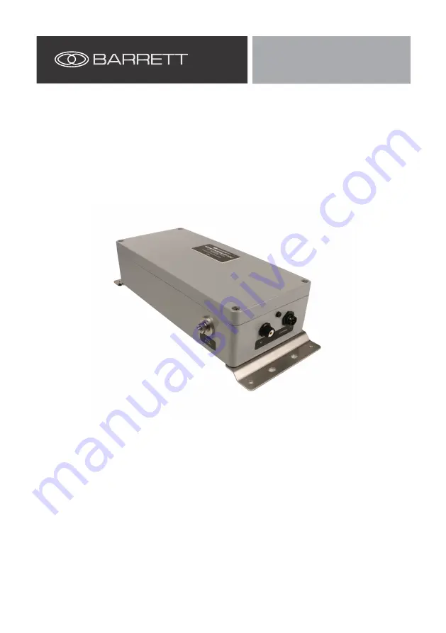
4015 Marine Automatic
Antenna Tuner
Operating Manual
4015


