background image

Manual

Value Series V-710IJ

Summary of Contents for Streamfeeder Value Series

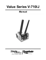
Page 1: ...Manual Value Series V 710IJ...

Page 2: ...d photocopied stored on a retrieval system or transmitted without the express written consent of Thiele Technologies Inc Streamfeeder Thiele Technologies Inc Streamfeeder 103 Osborne Road Minneapolis...

Page 3: ...tions iv Section 1 About the Machine 1 Section 2 Installing the Machine 5 Section 3 Preparing for Operation 11 Section 4 How to Operate 19 Section 5 Troubleshooting 23 Section 6 Inspection and Care 25...

Page 4: ...jury or death from an electrical haz ard if proper precautions are not taken TIP signifies information that is provided to help minimize problems in the installation or operation of the feeder NOTE pr...

Page 5: ...zardous voltage Contact will cause electric shock or burn Turn off and lock out power before servicing Moving parts can crush and cut Keep guards in place Lock out power before servicing Pinch point K...

Page 6: ...imum Product Size 3 75 W x 3 75 L in 95 x 95 mm Optional 2 5 W x 2 5 L in 63 x 63 mm Min Max Product Thickness 003 75 in 076 19 1 mm Belt Speed 5700 in min 144780 mm min Electrical Requirements 115 23...

Page 7: ...o prepare you for initial setup Descriptions are found in Table 1 1 Review the control panel components in Figure 1 2 to become fa miliar with names and locations of specific connectors switches and c...

Page 8: ...ts and helps push the material against the curvature of the gate assembly To achieve proper lift adjustment wing nuts and locking levers allow you to slide the wedge to various positions and angles Fe...

Page 9: ...3 Value Series V 710IJ Manual Figure 1 2A Control Panel Components Left and Right Side Views Control Panel Components Figure 1 2B Control Panel Components End View...

Page 10: ...set connector Cordset plugs into this IEC320 connector to provide feeder with power from a grounded and fused outlet Mode switch optional Note Included with optional external run input only This slide...

Page 11: ...r non vacuum transport base Information for a particular application typically includes procedures for basic parts removal feeder mounting and alignment and cable connections for power and control int...

Page 12: ...till attached Slide shaft back far enough on housing B to allow removal of jogging plate hopper guides 3 Loosen locking knob and slide jogging plate back hopper guide off of shaft and away from the su...

Page 13: ...bolt Reciprocating block 1 Locate the gate adjustment knobs Figure 2 3 and turn com pletely in a clockwise direction to raise hopping rollers 2 Then locate the vertical adjustment lever on the hopping...

Page 14: ...ing each in toward the side plates of the feeder until they gently touch Tighten side guide knobs to secure in position 1 Connect IEC320 end of power cord to the feeder at the power inlet module 2 Con...

Page 15: ...le 5 Interface the two bare wire leads at the opposite end of the interface cable to the vacuum base start stop circuit This involves splicing the black wire and red AC DC or dry con tact wire to the...

Page 16: ...ake sure the material is still under the hold down roller bearings and also resting on the vacuum base transfer section 5 Trap the feeder in between the side guides until they gently touch Tighten sid...

Page 17: ...wear loose clothing when operating the feeder Avoid making adjustments with loose or unsecured parts This can potentially damage parts Once the Streamfeeder V 710IJ Universal Friction Feeder is instal...

Page 18: ...the material Procedure To adjust the gate assembly for proper gap 1 Slide a single sheet of test product under the gate assembly It may be necessary to pull up on the adjustment knob to allow the piec...

Page 19: ...xt turn the other adjustment roller clockwise 1 8 turn 4 Repeat drag tests and adjust as needed until equal drag is achieved You may need to repeat this procedure after observ ing the feeder cycling r...

Page 20: ...5 Adjusting Gate Assembly for Low Tension Procedure Certain types of material may demand that you change the gate assembly from a high tension setting to a low tension setting for example irregular s...

Page 21: ...o move each side guide as needed 2 Grasp whichever side you wish to offset first and move into posi tion 3 Place a small stack of material in the hopper with edge of paper against offset guide 4 Move...

Page 22: ...not touching the table top A good starting point is to measure about 625 in 16 mm from the bottom sheet to front edge of table top Then as you test you can fine tune from this point 5 Make sure the e...

Page 23: ...this means a slight overlap of both the first sheet and the second sheet 125 in or 3 mm at the gate assembly area The overlap occurs as the bottom sheet is exiting and the next sheet is entering 3 If...

Page 24: ...18 Value Series V 710IJ Manual Notes...

Page 25: ...eed belts Also notice how the lifting helps to push the preshingled edges against the curvature of the gate assembly This section provides a sequence of operation for the V 710IJ Univer sal Friction F...

Page 26: ...1 Set the variable speed control to the lowest speed counter clockwise Feeder motor stops if turned completely counter clockwise 2 Start by slowly turning the control clockwise to gradually in crease...

Page 27: ...ation for proper adjustment procedures 4 Turn the feeder power back On by pushing the horizontal line at the Power On Off rocker switch Should you not be using the feeder for long periods of time foll...

Page 28: ...22 Value Series V 710IJ Manual Notes...

Page 29: ...ck height is down resulting in reduc tion of down pressure 2 Binding in side guides 3 Slippery feed belts 4 Sheet adhesion or interlocking between the bottom and next sheet Move switch to On or positi...

Page 30: ...Reduce weight Test again Rotate gate adjustment 1 8 turn to increase gap and manually test Review gate assembly adjustment procedure Review side guide setting procedure Move stack away from belt even...

Page 31: ...Belt Wear Check for visual signs of Walking Replace as required Cracking Replace as required Thinning Replace as required When performing initial feeder adjustments prior to operation always make sure...

Page 32: ...signs of Stretching Improper roller adjustment Ensuring Proper Timing and Drive Belt Tracking Check for visual signs of Misaligned timing pulleys Checking for Gate Assembly Wear Check for visual signs...

Page 33: ...ff feeder and remove power cord from outlet 2 Remove gate assembly from gate plate 3 Insert a screwdriver in slot on top of gate assembly and rotate screwdriver clockwise or counter clockwise 360 so a...

Page 34: ...f the belt repeat for each belt 5 Taking a dry portion of the cloth go back to the first feed belt cleaned and use moderate pressure against the belt for several revolutions to ensure the belt is drie...

Page 35: ...e gate assembly from gate bracket assembly 3 Apply a small amount of isopropyl alcohol to a soft cloth 4 Wipe across O rings or angled wedge if applicable First wipe in one direction then the other 5...

Page 36: ...30 Value Series V 710IJ Manual Notes...

Page 37: ...31 Value Series V 710IJ Manual 7 Mechanical Components...

Page 38: ...DESCRIPTION NUMBER 1 1 1 Wedge Guide Shaft 44633018 1 2 1 SHCS 10 32 X 5 8 LG 00002320 1 3 1 Wedge Block 44633014 1 4 1 T Nut Round 44633016 1 5 1 Knob 3 Lobe 10 32 X 5 8 LG 44633033 1 6 2 Ring Grip...

Page 39: ...Front 44675006 2 3 1 Lower Gate Support Bar 44841005 2 Gate J Hook 44841011 2 SHCS 8 32 X 5 8 LG 00002215 2 4 1 Upper Gate Support 44841006 2 5 2 Side Guide Adjust Clamp Rear 44841004 2 6 1 Pregate B...

Page 40: ...ART NUMBER QTY DESCRIPTION NUMBER 3 1 1 Side Guide Right 1424 Teflon 51050040 1 Label Warning 44600005 3 2 1 Side Guide Left 1424 Teflon 51050039 1 Label Warning 44600005 3 3 4 Screw FHS 10 32 X 1 2 L...

Page 41: ...35 Value Series V 710IJ Manual...

Page 42: ...xer Center Hub 44657009 2 Clip E 1 2 Waldes 00001155 2 Screw Socket Set 8 32 X 5 16 Cup Point 00002211 4 9 2 Roller 44872003 2 Adjustment Screw 44872005 2 Screw Socket Set 10 32 X 3 8 LG Nylon Tip 448...

Page 43: ...37 Value Series V 710IJ Manual...

Page 44: ...PTION NUMBER 5 1 6 Discharge Roller Collar 51277087 5 2 12 E Clip 3 8 00001150 5 3 6 R6 Bearing 23500095 5 4 3 Hold Down Shaft 51050238 5 5 3 Spring Pin 1 8 51312003 5 6 3 Hold Down Spring 51328001 5...

Page 45: ...39 Value Series V 710IJ Manual...

Page 46: ...Crown Drive Roller 23560208 2 Roller Feed 75 Inch Bore 23500126 1 Roller Flat Drive 23560206 2 Bearing Ball R8 23500094 2 Ring Grip 1 2 Waldes 00001115 12 Screw Socket Set 10 32 X 1 4 LG 00002216 4 S...

Page 47: ...2 4 Drive Crown Roller 51050006 1 Roller Crown Driven Narrow 44841033 1 Pulley 20T 1 2 Bore w Flange Driven 23500097 4 Bearing Ball R8 23500094 4 Clip E 1 2 Waldes 00001155 1 Screw Socket Set 10 32 X...

Page 48: ...Front Ear Right 51050102 7 5 2 Shield Lexan Smoked 51050072 2 Label Warning Roller Pinch Point 44600004 4 BHCS 10 32 X 2 LG 00003396 7 6 1 Discharge Support Bar 44841035 7 7 1 Shell Split Front Ear L...

Page 49: ...43 Value Series V 710IJ Manual...

Page 50: ...9 1 Motor 90VDC Assembly 115V Models Only 10501133 1 Motor 180VDC Assembly 230V Models Only 10502233 8 10 2 Mount Front Base Plate 44675003 8 11 1 Base Plate 51050237 8 12 1 Bracket Belt Tensioner 44...

Page 51: ...45 Value Series V 710IJ Manual...

Page 52: ...46 Value Series V 710IJ Manual 8 Electrical Components...

Page 53: ...47 Value Series V 710IJ Manual...

Page 54: ...48 Value Series V 710IJ Manual...

Page 55: ...49 Value Series V 710IJ Manual...

Page 56: ...50 Value Series V 710IJ Manual Notes...

Page 57: ......

Page 58: ...2009 Thiele Technologies Inc Streamfeeder Printed in the USA...

Reviews: