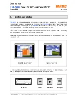
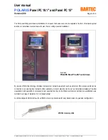
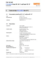
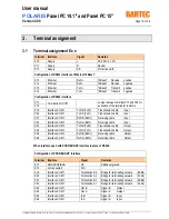
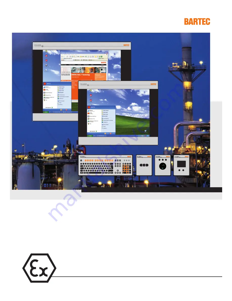
background image

Operator stations

          User Manual    Version 2.00

POLARIS  

Panel PC 19.1" and Panel PC 15"

Type 17-71V1-....

Summary of Contents for POLARIS Panel PC 15"

Page 1: ...Operator stations User Manual Version 2 00 POLARIS Panel PC 19 1 and Panel PC 15 Type 17 71V1...

Page 2: ...en Important note concerning transportation and shipping Sensitive equipment It is absolutely necessary to deliver the equipment in the original packaging in order to avoid damage occuring with the eq...

Page 3: ...USER MANUAL POLARIS Panel PC 19 1 Panel PC 15 English...

Page 4: ......

Page 5: ...nal assignment 16 3 1 Terminal assignment Ex e 16 3 2 Terminal assignment Ex i 17 3 3 Electrical installation 17 3 3 1 EMC notes 17 3 3 2 Interference suppression 18 3 3 3 Shielding 18 3 3 4 Connectio...

Page 6: ...CS 302ex 30 7 Installation additional components 31 7 1 Connection of Ex i keyboard to the POLARIS Panel PC 31 7 2 Connection of BARTEC USB Ex i memory stick 31 7 3 Connection of USB CD Rom drive 31 7...

Page 7: ...A resolution 1 024 x 768 pixels The Panel PCs are based on a fast Intel Pentium M processor and include all standard interfaces The 19 1 and 15 Panel PCs are the highlights of the POLARIS series These...

Page 8: ...g mounted installation By means of WLAN technology individual computers or network equipment such as printers or DSL access points can be connected to an existing local network LAN wirelessly or local...

Page 9: ...anel PCs as a standard Thus various software packages can be run on Panel PCs such as customer specific software or other standard visualisation software Of course the operator can also work with the...

Page 10: ...ntium M Processor 1 1 GHz Graphic memory 32 MB 512 MB RAM 20 GB memory Operating system Windows XP Embedded pre installed Open platform for customer specific visualisation software e g ProTool WIN CC...

Page 11: ...Characteristics data Panel PC 19 1 Display 19 1 TFT graphic display SXGA resolution 1 280 x 1 024 pixels 16 7 million colours Brightness 250 cd m2 Visible area approx 380 x 305 mm Contrast 700 1 Anti...

Page 12: ...ge 2 4 Characteristics data Panel PC 15 Display 15 TFT graphic display XGA resolution 1 024 x 768 pixels 262 144 colours Brightness 350 cd m2 Visible area approx 304 x 228 mm Contrast 400 1 Antireflec...

Page 13: ...ics data keyboard Type 17 71VZ 40 Ex protection type II 2G Ex ib IIC T4 II 2D tD A21 T 80 C IP 6X front side Certification IBExU05ATEX1117 X Keyboard Front panel fitting Dimensions 420 mm x 170 mm wei...

Page 14: ...nsions 130 mm x 170 mm weight x height Wall cut out 100 mm x 140 mm Installation depth 15 mm Weight approx 270 g 2 6 2 Trackball Ex protection type II 2G Ex ib IIC T4 II 2D tD A21 T 80 C IP 6X front s...

Page 15: ...PanelPC_19 15_Rev1 doc User manual for POLARIS Panel PC 19 1 and 15 Revision 1 Status January 3rd 2006 Technical data subject to change Dimensions and wall cut out for mouse trackball and touchpad 100...

Page 16: ...face COM 1 TxD A TxD Transmission cable Input X21 Interface COM 1 RxD B RxD Receiving cable Input X22 Interface COM 1 RxD A RxD Receiving cable Input X23 Interface COM 1 TxD B TxD Transmission cable O...

Page 17: ...WH BN VCC Supply voltage X5 PS2 GN YE GND Mass connected to protective earth X6 PS2 PK KB_CLK Keyboard clock signal X7 PS2 GR KB_DATA Keyboard data signal X8 PS2 BL MS_CLK Mouse clock signal X9 PS2 R...

Page 18: ...impaired The installation point should be as far as possible away from fields of electromagnetic interference This is especially important if there are frequency converters in the vicinity Under cert...

Page 19: ...ch cases it may prove advantageous to insulate the shielding from the sub D plug of the controller and connect it directly with the protective earth conductor by means of a cable that should be kept a...

Page 20: ...used If the shielding were connected at both ends the equipotential bonding current would flow to point A and this must be avoided at all costs as the resultant interference pulses could be passed on...

Page 21: ...PC 15 Version 2 00 Page 21 of 46 E_BMS790_POLARIS_PanelPC_19 15_Rev1 doc User manual for POLARIS Panel PC 19 1 and 15 Revision 1 Status January 3rd 2006 Technical data subject to change 4 Overview of...

Page 22: ...rostatic charging mechanism on the surface of the indicating terminals have to be excluded if they are stronger than manual rubbing e g cleaning by hand 5 2 Maintenance For the maintenance servicing a...

Page 23: ...f the backlight illumination Avoid installing in the immediate vicinity of switching devices or converters Note Only use heating systems which are certified for explosive areas The following factors s...

Page 24: ...ured 5 4 1 Recommended enclosure Stainless steel enclosure with wall thickness 2 mm In this case the reinforcement frame between the retaining clips and enclosure material should always be used Reinfo...

Page 25: ...pe 17 71VZ 40 Mouse Type 17 71VZ 10 Trackball Type 17 71VZ 20 Touchpad Type 17 71VZ 30 Hand held scanner BCS 302ex Type 17 21BA 0020 not possible in combination with touch screen Work may be performed...

Page 26: ...each of the supply cables The PE terminals on the back of the unit must be connected to the protective earth conductor It must be ensured that supply voltage is the same as that stated in this manual...

Page 27: ...Panel PC RS422 Modul Terminal compartment of the POLARIS Panel PC Controller PE TxD A TxD TxD B TxD RxD A RxD RxD B RxD RxD A RxD RxD B RxD TxD A TxD TxD B TxD Data In Data In Data Out Data Out Pins...

Page 28: ...B TxD TxD B TxD RxD B RxD TxD A TxD RxD A RxD RxD A RxD Data In Data Out Tx enable 17 18 See the interface description from the controller manufacturer for the relevant pin assignment of the controll...

Page 29: ...PROFIBUS DP interface of the POLARIS Panel PC The PROFIBUS DP interface may only be applied in combination with the visualisation software BMS Graf pro PROFIBUS DP module Terminal compartment of the P...

Page 30: ...Status January 3rd 2006 Technical data subject to change 6 4 Supply module for BCS 302ex Terminal connection diagram for hand held scanner BCS 302ex to supply module via a connector adapter Panel PC...

Page 31: ...se another USB stick than the BARTEC Ex i USB memory stick the USB interface can be destroyed 7 2 Connection of BARTEC USB Ex i memory stick Preconditions BARTEC USB Ex i memory stick it is not allowe...

Page 32: ...nuary 3rd 2006 Technical data subject to change 8 Configuration of POLARIS Panel PCs 8 1 Network Ethernet setup Precondition Physical connection connection of Ethernet cable to a network e g switch hu...

Page 33: ...elPC_19 15_Rev1 doc User manual for POLARIS Panel PC 19 1 and 15 Revision 1 Status January 3rd 2006 Technical data subject to change 4 To select the function Internet Protocol click on sub item Proper...

Page 34: ...User manual for POLARIS Panel PC 19 1 and 15 Revision 1 Status January 3rd 2006 Technical data subject to change 6 The following chart appears when the network and a DHCP server are available Chart 5...

Page 35: ...subject to change 8 2 Calibration of touch screen Double click on the touch screen symbol in the notification area The following window opens Select the function Calibrate bottom left to open the fol...

Page 36: ...icates which key function of the mouse is carried out when the touch screen is touched in this case it is the left mouse button when touching the symbol once the function changes once to the right mou...

Page 37: ...ional language 17 71VZ 40 0 Mouse 17 71VZ 1000 Trackball 17 71VZ 2000 Touchpad 17 71VZ 3000 Connection cable for keyboard and mouse 1 8 m 05 0068 0163 3 0 m 03 0068 0204 Connection cable for keyboard...

Page 38: ......

Page 39: ...S Panel PC 19 1 and Panel PC 15 EC Declaration of Conformity Page 39 of 46 E_BMS790_POLARIS_PanelPC_19 15_Rev1 doc User manual for POLARIS Panel PC 19 1 and 15 Revision 1 Status January 3rd 2006 Techn...

Page 40: ...Panel PC 19 1 and Panel PC 15 EG Baumusterpr fbescheinigung Page 40 of 46 E_BMS790_POLARIS_PanelPC_19 15_Rev1 doc User manual for POLARIS Panel PC 19 1 and 15 Revision 1 Status January 3rd 2006 Techn...

Page 41: ...Panel PC 19 1 and Panel PC 15 EG Baumusterpr fbescheinigung Page 41 of 46 E_BMS790_POLARIS_PanelPC_19 15_Rev1 doc User manual for POLARIS Panel PC 19 1 and 15 Revision 1 Status January 3rd 2006 Techn...

Page 42: ...Panel PC 19 1 and Panel PC 15 EG Baumusterpr fbescheinigung Page 42 of 46 E_BMS790_POLARIS_PanelPC_19 15_Rev1 doc User manual for POLARIS Panel PC 19 1 and 15 Revision 1 Status January 3rd 2006 Techn...

Page 43: ...Panel PC 19 1 and Panel PC 15 EC TYPE EXAMINATION CERTIFICATE Page 43 of 46 E_BMS790_POLARIS_PanelPC_19 15_Rev1 doc User manual for POLARIS Panel PC 19 1 and 15 Revision 1 Status January 3rd 2006 Tech...

Page 44: ...Panel PC 19 1 and Panel PC 15 EC TYPE EXAMINATION CERTIFICATE Page 44 of 46 E_BMS790_POLARIS_PanelPC_19 15_Rev1 doc User manual for POLARIS Panel PC 19 1 and 15 Revision 1 Status January 3rd 2006 Tech...

Page 45: ...Panel PC 19 1 and Panel PC 15 EC TYPE EXAMINATION CERTIFICATE Page 45 of 46 E_BMS790_POLARIS_PanelPC_19 15_Rev1 doc User manual for POLARIS Panel PC 19 1 and 15 Revision 1 Status January 3rd 2006 Tech...

Page 46: ...ARIS Panel PC 19 1 and Panel PC 15 Additional information Page 46 of 46 E_BMS790_POLARIS_PanelPC_19 15_Rev1 doc User manual for POLARIS Panel PC 19 1 and 15 Revision 1 Status January 3rd 2006 Technica...

Reviews: