background image

© Baxi Heating UK Ltd 2008
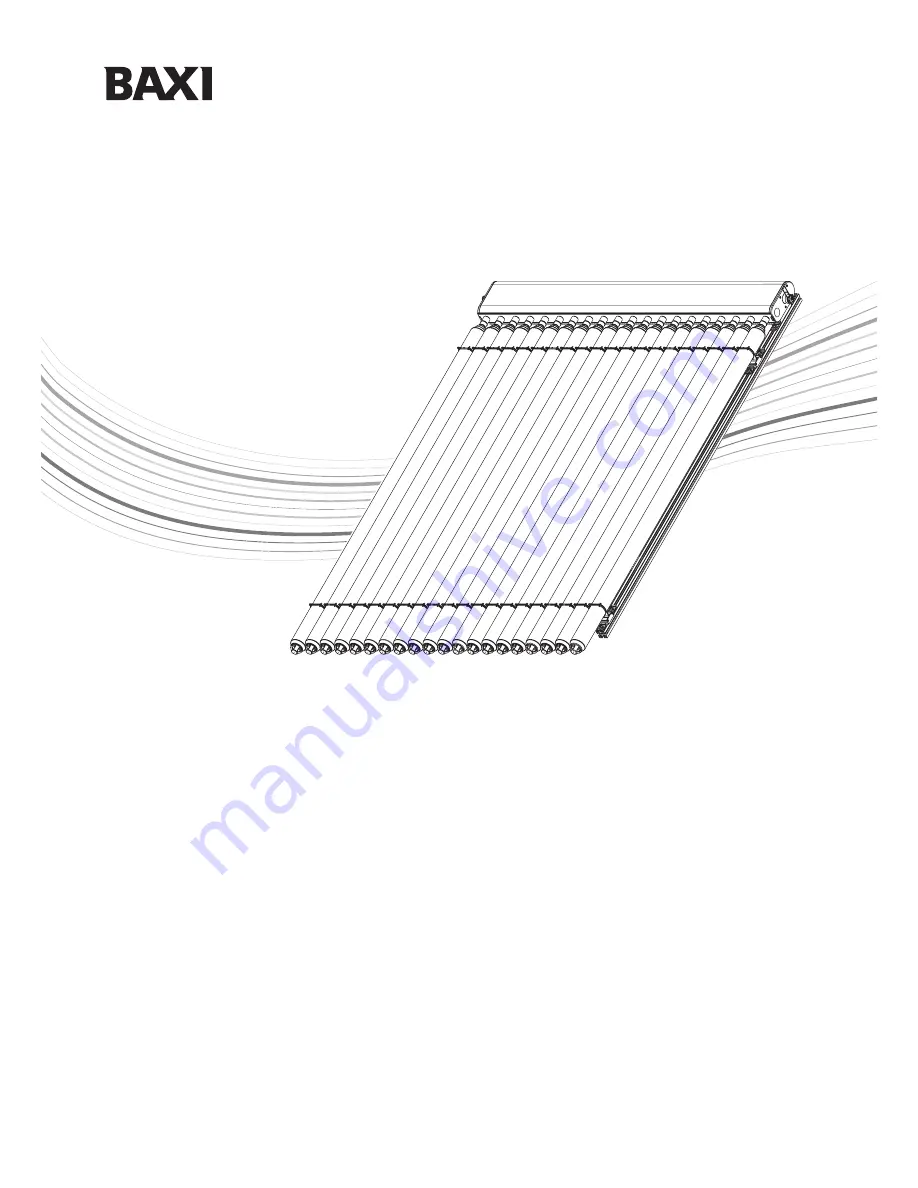
Solarflo

TM

Evacuated Tube  Collector

These instructions must be used in conjunction with the

Commissioning, Maintenance & Servicing Guide

Please read these instructions before installing or commissioning.

Solarflo

TM

(Solar Thermal Domestic Hot Water System) should only

be installed by a competent person.

PLEASE LEAVE THESE INSTRUCTIONS WITH THE USER

FOR SAFE KEEPING.

Installation Guide

Summary of Contents for Solarflo

Page 1: ...nction with the Commissioning Maintenance Servicing Guide Please read these instructions before installing or commissioning SolarfloTM Solar Thermal Domestic Hot Water System should only be installed by a competent person PLEASE LEAVE THESE INSTRUCTIONS WITH THE USER FOR SAFE KEEPING Installation Guide ...

Page 2: ...f any part of this publication should be made giving any details of the proposed use to the following address The Company Secretary Baxi Heating UK Ltd TheWyvern Business Park StanierWay Derby DE21 6BF Full acknowledgement of author and source must be given WARNING Any person who does any unauthorised act in relation to a copyright work may be liable to criminal prosecution and civil claims for da...

Page 3: ...ion heater The SolarfloTM water heating system provides all the principal components required for an efficient solar water heating system The sun s energy is captured by a series of solar collectors through which a special heat transfer fluid is pumped As the fluid passes through the collector its temperature is raised The heated fluid is circulated through a heat exchanger coil in the base of the...

Page 4: ...Ø Low iron transmission 0 92 Light transmittance 90 8 2 All dimensions shown in mm 0 2 4 6 8 40 80 120 160 Pressure Drop Pa Flow Rate l min 0 200 240 3 0 t u b e s 2 0 t u b e s Coefficients of efficiency 20 tubes determined in the sun simulator SUSI 1 η ηo a1 tm ta G a2 tm ta 2 G Based on aperture area absorber area ηo 0 773 0 830 a1 1 43 W m2 K 1 53 W m2 K a2 0 0059 W m2 K 0 0063 W m2 K Coeffici...

Page 5: ... 6 bar Pressure Relief Valve setting 6 bar Circulating Pump Grundfos UPS 25 60 Wilo ST 25 6 Circulating Pump voltage 230 240 V Power consumption Setting 1 40W Setting 2 60W Setting 3 80W Maximum Pump Head 6 metres Maximum Pump Capacity 4 5 m3 h 3 5 m3 h Flow meter scale 2 to 15 l min Features Air Separator Adjustable Control Valves Drain Point Temperature Gauges Flow Gauge 5 Baxi Heating UK Ltd 20...

Page 6: ...240V Capability per one switch output 1A 230VA for cos j 0 7 1 0 Total capability of all outputs 2A 460VA maximum Fuse protection fine wire fuse 5 x 20mm 2A T 2 amperes slow Features Menu driven operation System monitoring Solar gain measurement Suitable for flat plate and evacuated tube type collectors Auxiliary heat source control Can be used in a number of system configurations see Fig 27 NOTE ...

Page 7: ... Diameter Distance to nearest collector 15mm 8m 12m 22mm 4m 6m The size of the protection vessel should be at least the combined volume of the following Total Collector volume total pipe work volume from collector to protection vessel For positioning on protection vessel Fig 7 5 2 Solar Heat Transfer Fluid Pre mixed 40 glycol 60 water Solar thermal transfer fluid Based on1 2 propylene glycol with ...

Page 8: ...nt operates at 80 3 C Indirect models High limit thermal cut out operates at 85 C Wired in series with two port motorised valve supplied to provide primary over temperature protection when using auxiliary boiler coil All models Temperature and Pressure Relief Valve factory set to operate at 10 bar and 90 C High limit thermal cut out operating at 80 C 3 C at solar coil position Wired in series with...

Page 9: ...oil in coil design for improved performance Solar coil 25mm diameter stainless steel Coil in coil design and large surface area for improved performance Thermostat Direct models Element thermostat adjustable from 10 C to 70 C Indirect models Factory fitted cylinder thermostat from 10 C to 70 C Solar Factory fitted control pocket suitable for insertion of solar controller temperature probe Safety f...

Page 10: ...d to take suitable and sufficient steps to prevent the risk of a fall including selecting the most suitable work equipment in accordance with the regulations Mitigate the consequences of a fall where the risk of a person or object falling still remains take suitable and sufficient measures to minimise the distance and consequences of any fall Collective protection measures such as guard rails on s...

Page 11: ... have fewer than five employees you do not need to write anything down though it is useful to keep a written record of what you have done If you employ five or more people you must record the significant findings of your assessment You must also tell your employees about your findings You need to be able to show that a proper check was made that you considered who might be affected that you dealt ...

Page 12: ... materials used for installing temperature sensors sensor element conducting compound cables sealing and insulating materials must be suitably temperature resistant up to 200 C Solar Collector sensor may be extended using the 13m extension cable supplied as described in section 10 7 The sensor may be extended up to 50m but 0 75mm screened flex must be used see page 22 section 10 7 8 0 Installation...

Page 13: ...l drain valve 4 22mm compression fitting 4 off 5 Re Heat sensor auxiliary heat source 6 Solar Gain Module comprising Flowmeter and return temperature sensor 7 Sensor extension cable 13m not shown see Fig 24 Ancillary component cartons 8 Solar expansion vessel complete with mounting bracket assembly 9 Expansion vessel connecting flexible pipe 10 Expansion vessel self sealing connection 11 Thermosta...

Page 14: ...feed and return prevents the possibility of gravity circulation in the solar primary circuit A solar circulation pump Fig 15 Item 4 A flow gauge and regulator with fill drain valve and shut off valve Fig 15 Item 5 An air separator The heat transfer fluid is circulated by the solar circulation pump integrated in the hydraulic pump station Fig 15 In most instances the 20 litre container of Tyfocor L...

Page 15: ...ating systems use only pipes and fittings made from copper brass bronze brass or stainless steel Compression fittings only must be used All connections and joints must be resistant to temperatures quoted and resistant to glycol The height difference between the highest point in the pipework collector and the pump station may be a maximum of 15m this is called the static height If the static height...

Page 16: ...must be compatible with solar primary systems i e be resistant to glycol and temperatures up to 200ºC Insulating the pipework External pipework should be insulated with high temperature resistant materials and be protected against UV degradation Internal pipework especially through unheated spaces such as a loft space should also be insulated with high temperature resistant materials The SolarfloT...

Page 17: ...ease of access and operation of the controls see Fig 18 When choosing the site for the hydraulic station provision of a discharge pipe from the safety group and the location of the solar expansion vessel must be considered 9 6 Installing the wall brackets and pump station Remove the front insulation moulding Fig 19 Item 1 by pulling forward whilst holding the solar controller moulding Fig 19 Item ...

Page 18: ...hydraulic station A one metre head represents 0 1 bar However the charge pressure should be at least 1 5 bar The maximum static system head is 15m 1 5 bar 9 9 Connecting pipework Connect the flow and return pipes to the collectors and to the cylinder via compression fittings Fig 22 Item 1 Fittings are for 22mm o dia pipe Support the pump assembly when tightening connections Run a pipe Fig 22 Item ...

Page 19: ...pen the appliance as described in section 10 2 and hang it onto two screws Now two lower screws can be mounted Tighten all screws Do not overtighten to avoid damage to the controller backplate 10 2 Opening the controller No tools are required to open the controller The front of the controller is secured by two latches which engage with the controller backplate It can be opened by gently pulling th...

Page 20: ...ct separation of at least 3mm in both poles Additionally for unvented solar cylinders the controller should be wired via the solar coil over temperature cutout such that power is interrupted to the controller and hydraulic station in the event of the unvented cylinder overheating see Fig 26 Controllers are intended for the operation in 230 240V 50Hz mains Any motorised valves connected must be sui...

Page 21: ...r P1 Auxiliary heating 2 1 collector array 2 storage cylinder pump pump P1 P2 4 2 collector array 1 storage cylinder pump pump P1 P2 Fig 27 10 6 Solar Gain measurement For solar gain measurement it is necessary to fit the flowmeter and collector return sensor Tret as shown in the diagram in Fig 27 The collector return sensor must be securely attached to the return pipework using the securing ties ...

Page 22: ...grated into the boiler control circuit 3A Fused Supply L 1 1 7 10 3 1 2 3 E 2 3 4 5 6 7 8 9 10 Terminal Box Not supplied 2 3 2 3 5 1 2 3 7 6 N E L N E SL L N E DHWON CHON Boiler Terminal Strip Programmer 1 Solar Cylinder Auxiliary Controls 6 9 2 1 2 N Room Stat 1 8 Solar Controller Boiler Immersion 3 1 2 E Solar O Temp Cutout 3 8 2 PE L N Solar Differential Controller 11 A1 12 N T1 T2 T4 WMM 4 2 3...

Page 23: ...Cylinder SafetyValve OR 3 2 9 7 G Y BL WH GR 3 Port Mid PositionValve 5 OR See Fig 21 4 PL 4 L Relay A3 N 1 1 5 CoM Relay 8 No E Auxiliary heating by boiler with 3 port mid position valve system reheat control by solar controller 10 0 Installation of solar controller Key to abbreviations L Live N Neutral E Earth PL Pump Live SL Switched Live G Y Green and Yellow BL Blue BR Brown GR Grey OR Orange ...

Page 24: ...contained in this leaflet All goods are sold subject to our standard Conditions of Sale which are available on request BAXI A Trading Division of Baxi Heating UK Ltd 3879156 A Division of Baxi Group Brooks House Coventry Road Warwick CV34 4LL After Sales Service and Technical Enquiries 08700 603261 Our contact centre is open Monday to Friday 8am to 6pm Weekends and Bank Holidays 8 30am to 2pm We a...

Reviews: