


Summary of Contents for Centillion 100
Page 6: ...vi 893 01047 B ...
Page 12: ...xii 893 01047 B ...
Page 18: ......
Page 26: ......
Page 48: ......
Page 64: ......
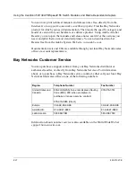
The Bay Networks Centillion 100 is a feature-rich networking device designed to enhance your connectivity. Its comprehensive Use Manual provides detailed instructions on installation, configuration, and troubleshooting. You can easily download this manual for free from our website, ensuring an optimal user experience for your network setup.
Page 6: ...vi 893 01047 B ...
Page 12: ...xii 893 01047 B ...
Page 18: ......
Page 26: ......
Page 48: ......
Page 64: ......


