background image

Summary of Contents for dark base 900

Page 1: ......

Page 2: ...Email service bequiet com Internet page www bequiet com Copyright You are not allowed to reproduce disclose publish or store the contents of this documentation or excerpts of it without the prior written consent of Listan be quiet is a registered trademark of Listan GmbH Co KG Other products and company names mentioned in this documentation may be the brands or trademarks of their respective owner...

Page 3: ... Controller manual 5V 12V PWM hub Cooler Height mm 185 Graphics Card Length mm 325 470 w o HDD trays PSU Length mm 150 284 PCI Slots 8 5 25 Bay 2 3 5 Bay 7 2 5 Bay 1 14 Cooling Fan mm rpm Front 2x SilentWings 3 140 1000 Rear SilentWings 3 140 1000 Optional Cooling Fan mm Front 1 x 140 w o ODD cage fan bracket included Top 3x 140 4 x 120 1x 180 Base 1x 120 2x 140 Radiator Support mm 120 140 180 240...

Page 4: ...et 1 Third fan on the front chassis mounting HDD 6 32 Screws 28 HDD slots mounting M3 Screws 8 SSD mounting Screws 6 32 14 MB mounting Stand off 14 4mm 3 E ATX mounting Thumb Screws M3 8 ODD mounting Cable Tie 6 Cable management HDD panel rubber grommet 1 Cable management LED Strip Pro version only 2 Illumination ...

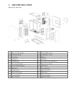
Page 5: ...nel O MB Tray D HDD Slots P SSD Tray E PSU Bracket Q Fan Speed Controller Board F Rear Panel Brackets R External Front Panel G Power Adapter Bracket S ODD Bezel H ODD Cage T Front Air Filter I Chassis Body U Front Panel Door J External Top Cover V Side Panel K Front I O Holder W Side Panel Filter L Base Air Filter X Side Panel Bezel ...

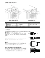
Page 6: ...Panel O SilentWings 3 fan D HDD Panel P M B Tray E HDD slots Q SSD Bracket F PSU Bracket R Fan Speed Controller Board G Rear Panel Brackets T External Front Panel H Power Adapter Bracket U ODD Bezel I ODD Cage V Front Air Filter J Chassis Body W Front Panel Door K External Top Cover L Front I O Holder ...

Page 7: ... manual USB 2 0 Find the USB 2 0 Headers pin connectors on the motherboard Plug in the wires according to the motherboard manual USB 3 0 Find the USB 3 0 Headers pin connectors on the motherboard Plug in the wires according to the motherboard manual Power switch Power LED HDD LED Reset switch These wires plug into the motherboard where all the front panel switch pin connectors functions are locate...

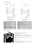
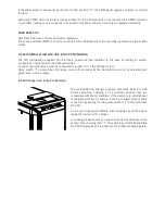
Page 8: ...AN CONTROLLER The fan controller has two modes of operation 1 Automatic operation For this the PWM signal of the MB is used and the speed of all fans connected PWM and 3 pin can be adjusted automatically through the MB In this mode the fan controller slider switch must be set to the first position 0 on the far left 2 Manual control When the fan controller slider switch is moved from its first posi...

Page 9: ...ttached adhesive strips To power them the lamps must be connected to socket D on the PCB panel 4 3 Using switch I and switches the lamps on and off and permits the illumination color to be selected red green blue white orange 4 6 QI Charger use only Pro Version The preinstalled Qi charger supplied with Dark Base Pro 900 allows cable free charging of all external devices that are compatible with th...

Page 10: ...uctions may cause harmful interference to radio communications However there is no guarantee that interference will not occur in a particular installation If this equipment does cause harmful interference to radio or television reception which can be determined by turning the equipment off and on the user is encouraged to try to correct the interference by one or more of the following measures Reo...

Page 11: ......

Reviews: