com
.
tom
RADIO 3.2 – Start-up Guide
In widely distributed systems or in envi-
ronments without network infrastructure
wireless solutions are required for the
simplest telecontrol/remote maintenance
functions.
The communication mechanism of the
com.tom devices ensures problem-free
use in all wireless networks without the
need for special SIM cards.
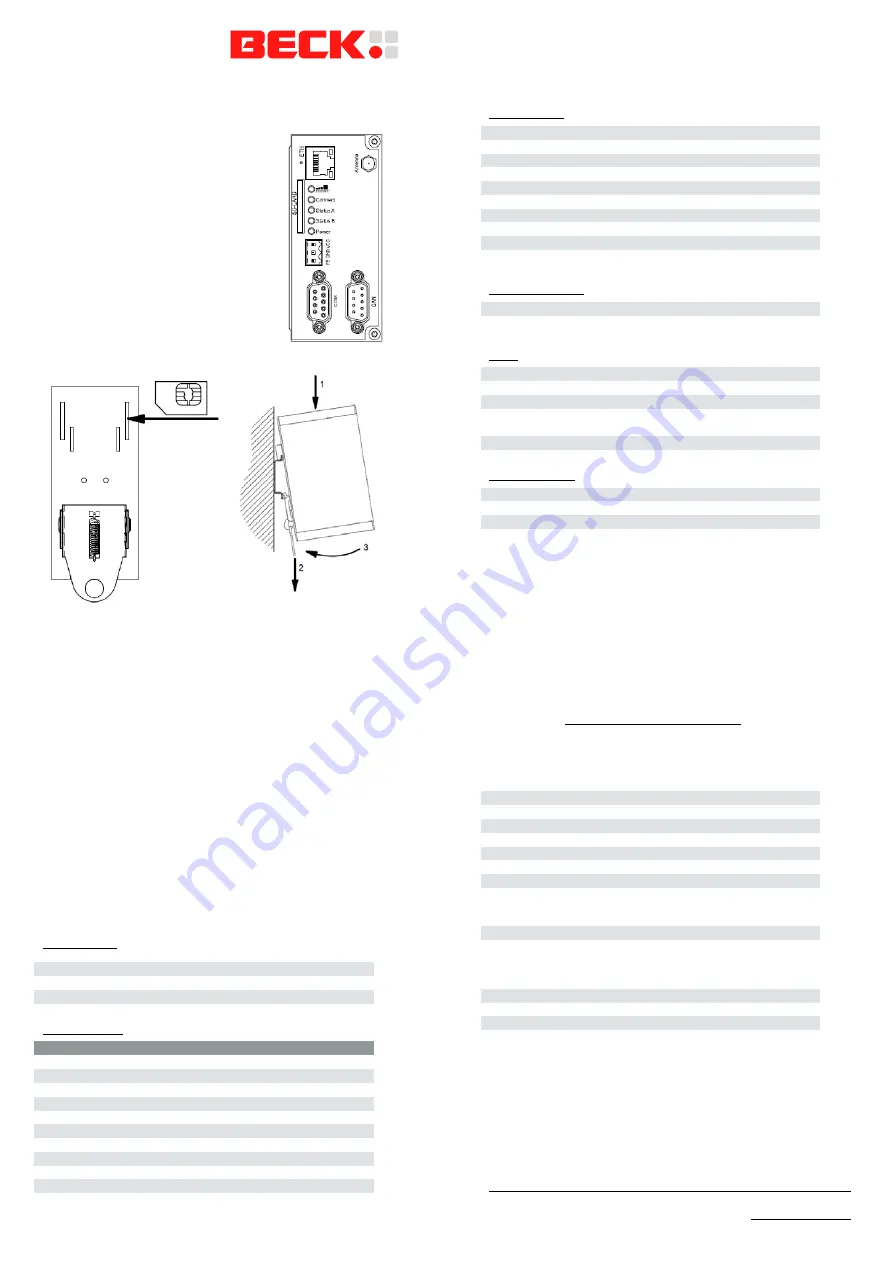
Device may only be put into service and
operated by qualified personnel.
The
device is designed for an installation on a
grounded 35 mm DIN rail in dry rooms.
Insert the SIM card in the
device’s rear before the installation on the DIN rail. The device must
be switched off.
Never use the device in areas where the operation of wireless
equipment is prohibited. The location for the antenna must guaran-
tee the recommended radiological limits (be at least 20 cm from
persons and other antennas).When the antenna is installed out-
doors the lightning protection standard VDE V0185 must be com-
plied with. The EMC lightning protection zone concept must be
observed. The device must be switched off during work on the
antenna. It cannot be guaranteed, that there will not be any harmful
interference for other devices. In case of interferences install the
device or the antenna in another location.
After the installation the housing of the device is connected with
functional earth.
The power supply must be a grounded circuit (PELV).
The power supply must be a limited power source according to
EN60950-1 cap. 2.5 or the device must be provided with an anti-
surge fuse of 2 A.
Pin Assignment
Power Supply
FE
Functional earth
GND Ground
VCC
24 VDC
Serial Interface
RS232
RS485
RS422
Pin 1
NC
A(-/Y)
A(TxD)
Pin 2
RxD
NC
NC
Pin 3
TxD
NC
NC
Pin 4
NC
NC
A'(RxD)
Pin
5 GND GND GND
Pin 6
NC
B(+/Z)
B(TxD)
Pin 7
RTS
NC
NC
Pin 8
CTS
NC
NC
Pin
9 NC NC B'(RxD)
Housing
Connected to functional earth
CAN Interface
Pin 1
NC
Pin 2
CAN_L
Pin 3
CAN_GND
Pin 4
NC
Pin 5
CAN_SHLD (optional)
Pin 6
CAN_GND
Pin 7
CAN_H
Pin 8
NC
Pin 9
NC
Housing
Connected to functional earth
Ethernet Interface
Green LED
Link indication
Yellow LED
Activity indication
LEDs
Modem
Modem is initialized
GSM/GPRS
GPRS Internet Connection successful
Status A
Communication with Portal successful
Status B
Program loaded (on) / executed (flashing) /
stopped (off)
Power
Device is powered
Other Interfaces
SD card interface
MMC/SD card
Antenna connector
SMA connector
SIM card interface
SIM card
Getting Started
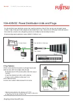
Wire the com.tom device according to the technical data.
Afterwards get the Getting Started documentation com.tom-
CODESYS at www.beck-ipc.com/gettingstarted and follow the
steps described there to put your com.tom device into opera-
tion.
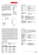
General Data
Size (W x L x H)
46 x 103 x 63 mm
Operating temperature
0 bis 55 °C
Electrical shock
Class III
Protection rating
IP20
EMC emission
IEC 61000-6-4
EMC immunity
IEC 61000-6-2
Compliance
CE, RoHS
Electrical Data
Supply voltage
24 VDC (
15 %)
Active current
0.120 mA
Scope of supply
1 Piece
com.tom Radio 3.2
1 Piece
Start-up guide
1 Piece
Connector 3-pin
1 Piece
Label MAC-ID
Copyright © 2013 Beck IPC GmbH
www.beck-ipc.com