background image

Centronic EasyControl

EC415A-III

en

Assembly and Operating Instructions

Wall transmitter 5-channel

Important information for:

• Fitters / • Electricians / • Users

Please forward accordingly!

These instructions must be kept safe for future reference.

Becker-Antriebe GmbH
Friedrich-Ebert-Straße 2-4
35764 Sinn/Germany
www.becker-antriebe.com

4034 630 451 0     21/01/2021   

Summary of Contents for Centronic EasyControl EC415A-III

Page 1: ... transmitter 5 channel Important information for Fitters Electricians Users Please forward accordingly These instructions must be kept safe for future reference Becker Antriebe GmbH Friedrich Ebert Straße 2 4 35764 Sinn Germany www becker antriebe com 4034 630 451 0 21 01 2021 ...

Page 2: ...uctions 4 Intended use 5 Explanation of displays and buttons 6 Explanation of functions 8 Commissioning of Centronic 9 Programming the transmitter 9 Installing the wall bracket 14 Changing batteries 15 Cleaning 15 Technical data 15 What to do if 16 2 en ...

Page 3: ...ons and incorrect installation which are not in accordance with these and our other instructions can result in serious injuries e g crush ing of limbs Therefore structural modifications may only be carried out with our prior approval and strictly in accordance with our instructions particularly the information contained in these Assembly and Operating Instructions Any further processing of the pro...

Page 4: ...rol units Observe all pertinent country specific regulations Dispose of used batteries properly Only replace the battery with one of the same type see Technical Data Caution Keep people out of the system s range of travel If the system is controlled by one or more transmitters the system s range of travel must always be visible during operation Device contains small parts that can be swallowed 4 e...

Page 5: ...s or property or which contain safety devices to eliminate such risks The operator is not protected from interference from other telecommu nications systems and terminal equipment e g even from radio con trolled systems which are properly operated in the same frequency range Only connect radio receivers to devices and systems approved by the manufacturer Ensure that the control unit is not install...

Page 6: ...Explanation of displays and buttons 9 10 11 5 4 3 2 1 8 7 6 6 en ...

Page 7: ...1 button 2 button STOP 3 Channel transmission pilot lights 4 button 5 Channel selection button 6 Battery 7 programming button 8 Commissioning LED 9 Wall transmitter 10 Frame 11 Wall bracket 7 en ...

Page 8: ...ected using the channel selection button The indi vidual channels are indicated by the corresponding channel indicator lamp lighting up If all the channel indicator lamps light up at the same time a cent ral command can be transmitted Transmission pilot light A radio signal is indicated by the transmission pilot light lighting up The trans mission pilot light flashes while transmitting if the batt...

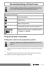
Page 9: ...n on the transmitter Receiver confirms once or multiple times by clicking or shifting Programming the transmitter Putting the receiver into programming mode Follow the Assembly and Operating Instructions for the re ceiver Switch off the power supply to the receiver for 5 seconds then switch it back on or Operate the programming button or the radio switch of the receiver The receiver is now in prog...

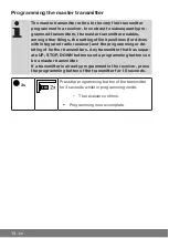
Page 10: ...s with integrated radio receiver and the programming or de leting of further transmitters Any transmitter that has separ ate UP STOP DOWN buttons and a programming button can be a master transmitter If a transmitter is already programmed in the receiver press the programming button of the transmitter for 10 seconds 3s Press the programming button of the transmitter for 3 seconds whilst in programm...

Page 11: ...n for 3 seconds The receiver confirms 3s Now press the programming button of a new transmitter which has not yet been programmed in the radio receiver for 3 seconds Doing so activ ates the programming mode of the radio receiver for a new transmitter for 3 minutes The receiver confirms 3s Now re press the programming button of the new transmitter you wish to program for 3 seconds The receiver confi...

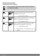
Page 12: ...amming button on the master transmitter for 3 seconds The receiver confirms 3s Now press the programming button of the trans mitter to be deleted for 3 seconds The receiver confirms 10s Then re press the programming button of the transmitter to be deleted for 10 seconds The receiver confirms The transmitter is now deleted from the radio receiver 12 en ...

Page 13: ...onds The receiver confirms 3s Re press the programming button on the master transmitter for 3 seconds The receiver confirms 10s Then press the programming button on the mas ter transmitter again for 10 seconds The receiver confirms All transmitters except the master transmit ter are now deleted from the radio receiver 13 en ...

Page 14: ...ing mode To do so after switching the power back on execute a drive or stop command using the transmitter for the given receivers 10s Press the programming button of the new master transmitter when programming mode is active for 10 seconds The receiver confirms The new master transmitter has now been programmed and the old master transmitter overwritten Installing the wall bracket Caution If mount...

Page 15: ...se aggressive cleaning agents that may damage the surface Technical data Rated voltage 3 V DC Battery type CR 2430 Degree of protection IP 20 Permissible ambient temperature 10 C to 55 C Maximum emitted transmission output 3 mW Radio frequency 915 3 MHz The maximum transmitter range on and in the building is up to 15 m and up to 150 m in the open 15 en ...

Page 16: ...ive does not move Insert a new battery Insert the battery correctly Reduce distance from receiver Transmitter is not programmed into receiver Program transmitter Required tubular drive receiver is not responding Select correct channel 16 en ...

Page 17: ...17 ...

Page 18: ...18 ...

Page 19: ...19 ...

Page 20: ......

Reviews: