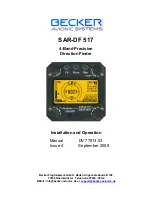
background image

SAR-DF 517

4-Band Precision

Direction Finder

Installation and Operation

Manual

DV 77513.03

Issue 4             September 2006

Becker Flugfunkwerk GmbH · Baden Airpark ·Gebäude B 108

 77836 Rheinmünster · Telephone 07229 / 305-0

E-Mail : info@becker-avionics.de or 

support@becker-avionics.de

Summary of Contents for SAR-DF 517

Page 1: ...ion Finder Installation and Operation Manual DV 77513 03 Issue 4 September 2006 Becker Flugfunkwerk GmbH Baden Airpark Geb ude B 108 77836 Rheinm nster Telephone 07229 305 0 E Mail info becker avionic...

Page 2: ...2006 List of effective pages Page No Date Page No Date Titlepage ISO 9001 I 1 I 4 1 1 1 10 2 1 2 12 3 1 3 10 09 2006 09 2006 09 2006 09 2006 09 2006 DV 77513 03 Article Number 0551 295 071 2001 by Bec...

Page 3: ...ce with our quality management system standards ISO 9001 Certified Quality System Das Becker Qualit tsmanagementsystem ist zertifiziert nach The Becker quality management system is certified according...

Page 4: ...ritime band 1 7 1 5 Scope of delivery 1 9 1 6 Accessories 1 9 1 7 Manuals 1 9 Fig 1 1 4 Band precision direction finder system 1 2 Section 2 Installation Page 2 1 General 2 1 2 1 1 Inspection before i...

Page 5: ...n procedure selection of operating mode 3 1 3 2 2 General functions 3 2 3 3 Bearing mode 3 3 3 3 1 Operating elements in bearing mode 3 3 3 3 2 Display in bearing mode 3 4 3 3 3 Scanning mode when bea...

Page 6: ...13 03 Issue 4 09 2006 Page I 3 Fig 3 6 Display page 3 Bearing Display as Text 3 5 Fig 3 7 Display Cospas Sarsat analyse page4 3 7 Fig 3 8 Display edit menu page 5 3 8 Fig 3 9 Menu of adjustable freque...

Page 7: ...SAR DF 517 DV 77513 03 Issue 4 09 2006 Page I 6 Blank...

Page 8: ...multiband type 118MHz 410MHz working with the physical Doppler Effect It offers the possibility to bear and analyse traditional emergency frequencies in the UHF and VHF band and the maritime radio ba...

Page 9: ...der It can be seen as an interface between the direction finder and the operator The Antenna Unit AU contains the direction finder prober the heart of the whole system comprising four modules This Ant...

Page 10: ...y stability 2 0 ppm f f 2 10 6 at temperature range 20 C 60 C Receiving channels 8 four of them are free adjustable Receiving frequencies Emergency mode or see type plate for 121 500 MHz VHF special c...

Page 11: ...ms with sufficient receiving field strength LC graphic display 128x64 dots supertwist transflective extended range of temperature dark blue display on yellow green background lit up Free adjustable ex...

Page 12: ...he dimming operates in night mode Max of brightness ca 2 of day default mode Impedance of input 50 k Pin 4 NVG status line only at SAR DF 517 N with NVG frontpanel otherwise don t connect Low active A...

Page 13: ...40 C 60 C storage temperature 55 C 80 C Note 3 For temperatures lower than 10 C a warm up period up to 15 min is necessary Protective System Antenna IP 67 1 3 4 Mechanical data and weights Weights Di...

Page 14: ...60 950 MHz 8 156 400 MHz 9 156 450 MHz 10 156 500 MHz 11 156 550 MHz 12 156 600 MHz 13 156 650 MHz 14 156 700 MHz 15 156 750 MHz 16 156 800 MHz 17 156 850 MHz 18 156 900 MHz 161 500 MHz 19 156 950 MHz...

Page 15: ...525 MHz 71 156 575 MHz 72 156 625 MHz 73 156 675 MHz 74 156 725 MHz 75 156 775 MHz 76 156 825 MHz 77 156 875 MHz 78 156 925 MHz 161 525 MHz 79 156 975 MHz 161 575 MHz 80 157 025 MHz 161 625 MHz 81 15...

Page 16: ...nnector D Sub display unit Cable connector D Sub power supply Cable harness 5 Article No 0542 581 954 Consist of 5m Cable completed Cable connector round antenna and unconnected on D Sub display unit...

Page 17: ...SAR DF 517 Page DV 77513 03 Issue 4 09 2006 1 10 Blank...

Page 18: ...pping Before installing the dispaly unit and antenna unit in an aircraft carry out a visual inspection for any transit damage paying particular attention to the following Dirt dents scratches corrosio...

Page 19: ...into a front panel by the means of this mounting drawing Fig 2 2 Mounting drawing of the display unit 79 5 mm 3 13 inch 82 mm 3 23 inch 82 mm 3 23 inch 43 3 mm 1 7 inch 21 1 mm 0 83 inch 28 mm 1 1 in...

Page 20: ...to ground has to be applied between vehicle body and antenna Fig 2 3 Mounting drawing of the antenna 8 x holes for mounting the antenna unit on the body of the vehicle aircraft In this hatched area th...

Page 21: ...63 inch 3 mm 0 12 inch 7 mm 0 28 inch 10 mm 0 39 inch 185 mm 7 28 inch 82 mm 3 23 inch 157 mm 6 18 inch 270 mm 10 63 inch 3 mm 0 12 inch 7 mm 0 28 inch 10 mm 0 39 inch 185 mm 7 28 inch 82 mm 3 23 inc...

Page 22: ...possible from other antennas This is essential to avoid signal distortion and thus inaccurate bearing indication Furthermore the antenna and its feeders must no be located in the vicinity of sources o...

Page 23: ...fuse or circuit breaker must be installed in the power supply line Before switching on the equipment carefully check the wiring making particularly sure that the positive and negative poles have not b...

Page 24: ...R DF 517 DV 77513 03 Issue 4 09 2006 Page 2 7 Fig 2 6 Interwiring diagram 6 pol Amphenol plug female PTG06SE10 6S SQ Max length of cable ca 30m GND connected to cable shield 9 pol Sub D plug female ma...

Page 25: ...out in the air It is also necessary to establish whether any equipment in the aircraft electrical system is generating interference Functional check after installation For this test the following Mea...

Page 26: ...uipment at the signal generator Set an output frequency of 121 500 MHz Level 50 dB V AM Off FM Off or use a test PLB on test frequency using a 20 dB attenuation c Switch on the Display unit adjust to...

Page 27: ...rference compare with post installation check as described above Should the reading be influenced by local interference trace the source by systematically switching off the electronic equipment genera...

Page 28: ...ve power supply lead close to the item concerned is suggested in order to isolate the harmonics of the chopper frequency from the aircraft wiring system 3 RF interference Interference resulting from t...

Page 29: ...SAR DF 517 Page 2 12 DV 77513 03 Issue 4 09 2006 Blank...

Page 30: ...e with the clearly arranged layout With the exception of the upper page rotary switch and the ON OFF push button the function of the operating elements depends on the active page All relevant adjustme...

Page 31: ...l operating elements of the display unit 1 DIM In order to adjust internally the background brightness of the display press simultaneously the REP key while selecting the brightness with the PAGE rota...

Page 32: ...de The device works in the bearing mode As soon as a signal is received receiving level above squelch level the unaveraged maximal bearing values spread are indicated and if interpretable the averaged...

Page 33: ...e loss of a receiving signal The averaging procedure may couse a drag error which may be disturbing after quick changes of course In this case the indicated bearing value lags by the real bearing valu...

Page 34: ...e range the worse is the received signal The excellent averaging procedure effects good bearing results even with a spread of 45 3 Receiving level field strength of the signal in the range of 0 to 100...

Page 35: ...ear range may obtaind a bearing faster with a continuous signal For this purpose in the scanning mode the 406 MHz pulse and at the same time two other emergency frequencies can be for a continuous sca...

Page 36: ...message will be displayed 4 Frame SYNC OK normal CospasSarsat signal or SLFTEST CospasSarsat signal in auto test mode All 24 synchronising bits have been received correctly 5 Applied CP SARSAT protoc...

Page 37: ...nals thus enabling a good signal analysis normal TimeHold value 10 secs 6 Offset electronic correction rotation of the bearing antenna Adjustment delivers correspondingly changed bearing values normal...

Page 38: ...ncy MHz kHz 2 rotary switch changing the frequency Confirm the changed value by pressing pushbutton STORE 3 STORE Pushbutton to confirm changed values Fig 3 9 Menu of adjustable frequencies page 6 4 R...

Page 39: ...f transmitter Error 5 E5 OSCILAT antenna error in synthesizer oscillator of receiver in Antenna Unit Error 6 E6 NO DCU Connection Display Antenna No serial data from Display Unit to Antenna Unit Error...

Reviews: