background image

Documentation

BK9053, BK9103

Bus Coupler for PROFINET

2.3.0
2019-08-15

Version:
Date:

Summary of Contents for BK9053

Page 1: ...Documentation BK9053 BK9103 Bus Coupler for PROFINET 2 3 0 2019 08 15 Version Date ...

Page 2: ......

Page 3: ...temperature range 21 3 8 ATEX Special conditions extended temperature range 22 3 9 ATEX Documentation 23 4 Parameterization and commissioning 24 4 1 Start up behaviour of the Bus Coupler 24 4 2 DIP switch settings 25 4 3 Network classes 27 4 4 IP address 28 4 4 1 IP address and PROFINET name 28 4 4 2 Configuration with KS2000 28 4 4 3 Setting the IP Address Using the Beckhoff BootP Server 30 4 4 4...

Page 4: ...Table of contents BK9053 BK9103 4 Version 2 3 0 8 Appendix 45 8 1 General operating conditions 45 8 2 Bibliography 47 8 3 List of Abbreviations 47 8 4 Support and Service 48 ...

Page 5: ...fication of products that have already been supplied may be made on the basis of the data diagrams and descriptions in this documentation Trademarks Beckhoff TwinCAT EtherCAT EtherCAT G EtherCAT G10 EtherCAT P Safety over EtherCAT TwinSAFE XFC XTS and XPlanar are registered trademarks of and licensed by Beckhoff Automation GmbH Other designations used in this publication may be trademarks whose us...

Page 6: ...or trained specialists in control automation and drive engineering who are familiar with the applicable national standards Description of instructions In this documentation the following instructions are used These instructions must be read carefully and followed without fail DANGER Serious risk of injury Failure to follow this safety instruction directly endangers the life and health of persons W...

Page 7: ...and hardware versions Documentation Version BK9053 BK9103 Firmware Hardware Firmware Hardware 2 2 0 B9 06 C1 11 2 1 0 B9 06 C1 11 2 0 0 B8 04 C0 11 1 3 1 B5 00 BD 06 1 3 0 B2 00 BA 06 1 2 0 B1 00 B7 06 1 1 0 B2 00 1 0 0 B0 00 Minimum hardware required for update You can determine which firmware was fitted when the Bus Coupler left the factory from the adhesive label underneath see the fifth and si...

Page 8: ...4 IO Link master B8 I M2 and I M3 supported B7 HD terminals included B6 KL2791 KL1212 KL2641 implemented Step 7 online view supported B5 Alias name revised B4 LLDP SNMP implemented I M0 I M1 I M4 supported B3 Support for all KL terminals B2 Support for new Bus Terminals implemented KL3xxx and KL4xxx can now also be entered in compact form B0 First published BK9053 Firmware Description Supported te...

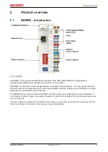
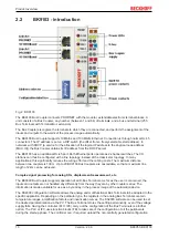
Page 9: ...ed in standard Ethernet networks and networked via commercially available switches Linking to any PROFINET controller takes place via the GSDML basic device file The BK9053 Bus Coupler connects PROFINET with the modular extendable electronic terminal blocks A unit consists of a Bus Coupler any number between 1 and 64 of terminals 255 with K bus extension and one end terminal The Bus Couplers recog...

Page 10: ...es the wiring effort and the cabling costs The maximum distance between two couplers is 100 m Up to 20 BK9103 Bus Couplers are cascadable so that a maximum line length of 2 km can be achieved Complex signal processing for analog I Os displacement measurement etc The BK9000 Bus Coupler supports operation of all K Bus Terminals As far as the user is concerned the inputs and outputs are not handled a...

Page 11: ... of input data and 512 bytes of output data Bus connection 1 x RJ45 2 x RJ45 Power supply 24 VDC 15 20 Current consumption 70 mA total K bus current 4 max 500 mA Starting current approx 2 5 x continuous current K Bus power supply up to 1750 mA Power contact voltage maximal 24 VDC Power contact current load maximal 10 A Dielectric strength 500 V power contact supply voltage Ethernet fieldbus Recomm...

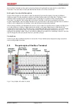
Page 12: ...s system are supported Mounting on standardized mounting rails The installation is standardized thanks to the simple and space saving mounting on a standardized mounting rail EN 60715 35 mm and the direct wiring of actuators and sensors without cross connections between the terminals The consistent labelling scheme also contributes The small physical size and the great flexibility of the Bus Termi...

Page 13: ...in each Bus Terminal and are retained in the event of voltage drop out Fieldbus K bus and I O level are electrically isolated If the exchange of data over the fieldbus is prone to errors or fails for a period of time register contents such as counter states are retained digital outputs are cleared and analog outputs take a value that can be configured for each output when commissioning The default...

Page 14: ...inals in use Depending on function the Bus Terminals are 12 or 24 mm wide The front wiring increases the total height of 68 mm by about 5 to 10 mm depending on the wire thickness Mechanical data BKxxxx BCxxxx BKxx50 BCxx50 BXxxxx LCxxxx Design form compact terminal housing with signal LED Material Polyamide PA 6 6 Polyamide PA 6 6 Polycarbonate Polyamide PA 6 6 Dimensions W x H x D 49 x 100 x 68 m...

Page 15: ...ible between the housings Fixing of mounting rails The locking mechanism of the terminals and couplers extends to the profile of the mounting rail At the installation the locking mechanism of the components must not come into conflict with the fixing bolts of the mounting rail To mount the mounting rails with a height of 7 5 mm under the terminals and couplers you should use flat mounting connecti...

Page 16: ...minals are implemented in spring force technology Connect the cables as follows 1 Open a spring loaded terminal by slightly pushing with a screwdriver or a rod into the square opening above the terminal 2 The wire can now be inserted into the round terminal opening without any force 3 The terminal closes automatically when the pressure is released holding the wire safely and perma nently Shielding...

Page 17: ...the aid of a connecting cable and the KS2000 configuration software The interface permits the Bus Terminals to be configured for example adjusting the amplification factors of the analog channels The interface can also be used to change the assignments of the bus terminal data to the process image in the Bus Coupler The functionality of the configuration interface can also be reached via the field...

Page 18: ...he hub using a standard Ethernet cable and connect the hub again using a standard Ethernet cable to the Bus Terminal controller Connection via a switch is done in the same way Direct Ethernet connection from PC to BK910x Fig 8 Direct Ethernet connection from PC to BK910x A standard Ethernet cable must be used for connecting the PC directly with the Bus Terminal Controller Pin assignment of the RJ4...

Page 19: ...ternal switch facilitates creation of a line topology A maximum of 20 BK9103s can be connected in series in a physical line The maximum distance between two BK9103s is 100 m The maximum overall line length is therefore 2 km No further switch may be included in this line Fig 9 Ethernet topology with several BK9103 in two lines The BK9103 also enables a classic star topology to be set up In this cas...

Page 20: ... The use of switches as star couplers enables collisions to be reduced Using full duplex connections they can even be entirely avoided 100BaseT Twisted pair cable for 100 Mbaud It is necessary to use a higher cable quality and to employ appropriate hubs or switches in order to achieve the higher data rate 10BaseF The 10BaseF standard describes several optical fiber versions Short description of th...

Page 21: ... to the actual measured temperature values Observe the permissible ambient temperature range of 0 to 55 C for the use of Beckhoff fieldbus compo nents standard temperature range in potentially explosive areas Measures must be taken to protect against the rated operating voltage being exceeded by more than 40 due to short term interference voltages The individual terminals may only be unplugged or ...

Page 22: ...s Measures must be taken to protect against the rated operating voltage being exceeded by more than 40 due to short term interference voltages The individual terminals may only be unplugged or removed from the Bus Terminal system if the supply voltage has been switched off or if a non explosive atmosphere is ensured The connections of the certified components may only be connected or disconnected ...

Page 23: ...f the Beckhoff terminal systems in potentially explosive ar eas ATEX Pay also attention to the continuative documentation Notes about operation of the Beckhoff terminal systems in potentially explosive areas ATEX that is available in the download area of the Beckhoff homepage http www beckhoff com ...

Page 24: ...letion of the self test the Bus Coupler starts to test the attached Bus Terminals the Bus Terminal Test and reads in the configuration The Bus Terminal configuration is used to generate an internal structure list which is not accessible from outside In case of an error the Bus Coupler enters the Stop state Once the start up has completed without error the Bus Coupler enters the fieldbus start stat...

Page 25: ...vice is PROFINET compliant if DIP switches 18 are OFF and DIP switches 9 and 10 are ON All other modes are available as options BK9053 Right switch position ON Left switch position OFF Fig 12 DIP switches of the BK9053 The device is PROFINET compliant if DIP switches 18 are OFF and DIP switches 1 and 2 are ON All other modes are available as options PROFINET name via DIP switch The name is formed ...

Page 26: ...tes of MAC ID DHCP DIP switch 1 to 8 set to ON PN name via DIP switch 1 to 8 IP address and SNM via DHCP PN name via DIP switch 1 to 8 IP address and SNM via DHCP DNS name bk9103 xxyyzz xxyyzz last 3 bytes of MAC ID 1 0 BootP PN name from memory IP address and SNM via BootP PN name becomes empty string IP address via BootP 1 1 PROFINET compliant DIP switch 1 to 8 set to OFF PN name from memory IP ...

Page 27: ...nodes per network A 7 126 24 16 777 214 B 14 16 382 16 65 536 C 21 2 097 150 8 254 Unique IP address An IP address must be unique within the entire connected network Fig 13 Network classes Identical network class In a communication with another Ethernet devices the IP address set must have the same network class Sample Your PC has the address 172 16 17 55 which means the coupler must have the ad d...

Page 28: ...s KS2000 Addressing using the KS2000 configuration software and DIP switches 28 KS2000 configuration software and KS2000 cable BootP Addressing via BootP server 30 BootP Server DHCP Addressing via DHCP server 31 DHCP Server 4 4 2 Configuration with KS2000 The KS2000 configuration software from version 3 2 8 can be used to set the TCP IP address in a dialog box or it can be written directly into th...

Page 29: ...Parameterization and commissioning BK9053 BK9103 29 Version 2 3 0 Software reset A software reset is required to save changes in the Bus Coupler tables A hardware reset power on off is not sufficient ...

Page 30: ...dress assigned by the BootP server is only valid until the Bus Coupler is switched off The BootP server must assign a new IP address to the Bus Coupler at the next cold start The address is however retained through a software reset of the Bus Coupler Beckhoff BootP server Beckhoff supply a BootP server for Windows 98 ME NT4 0 NT2000 and XP The installation version of the Beckhoff TwinCAT CD can be...

Page 31: ...art of an address space Zeros indicate that part of the address space which is available for the host IDs Description Binary representation Decimal representation IP address 10101100 00010000 00010001 11001000 172 16 17 200 Subnet mask 11111111 11111111 00010100 00000000 255 255 20 0 Network ID 10101100 00010000 00010000 00000000 172 16 16 0 Host ID 00000000 00000000 00000001 11001000 0 0 1 200 St...

Page 32: ...Parameterization and commissioning BK9053 BK9103 32 Version 2 3 0 Fig 16 Testing the IP address using the Ping command ...

Page 33: ...t process image cannot be configured e g KL9100 KL9020 KL9050 KL9010 For digital Bus Terminals at least one byte is reserved in all cases Example KL1xx2 2 digital inputs 8 bit with the first two bits 0 1 reserved for the terminal Bits 2 7 are not used Complex Bus Terminals are represented with an input and output process image Sample KL3001 1 analog input 1 Byte Control or Status Information one e...

Page 34: ...nfiguration Enter the name of the PN device e g bk9103 1 bk must be lower case Set DIP switches 1 9 and 10 of the BK9103 to ON and all others to OFF then switch on the Coupler Fig 19 Step 7 enter the name for the PROFINET device The configuration will now look as follows for example Load the configuration into your control system ...

Page 35: ...Configuration BK9053 BK9103 35 Version 2 3 0 Fig 20 Step 7 display of the configuration in the controller ...

Page 36: ... looks after the address management finding and assigning MAC IDs segmentation and routing Like the Ethernet protocol IP does not guarantee that the data is transported data packets can be lost or their sequence can be changed TCP IP was developed to provide standardized reliable data exchange between any numbers of different networks TCP IP is thus substantially independent of the hardware or sof...

Page 37: ...he MAC ID can for example be used for the BootP protocol in order to set the TCP IP number This involves sending a telegram containing the information such as the name or the TCP IP number to the corresponding node You can read the MAC ID with the KS2000 configuration software The Internet Protocol IP The internet protocol IP forms the basis of this data communication IP transports data packets fr...

Page 38: ...ollowing protocols can run on top of TCP IP or UDP ADS ModbusTCP Both of these protocols are implemented in parallel on the Bus Coupler so that no configuration is needed to activate the protocols Fig 22 Protocols running on top of TCP IP and UDP IP ADS can be used on top of either TCP or UDP but ModbusTCP is always based on TCP IP ...

Page 39: ...ath may consist of at most five segments and four repeater sets two repeater pairs Up to three of these segments may be coaxial segments to which the stations are connected The remaining segments must consist of point to point connections these are also known as IRL inter repeater link connections Cabling guidelines Structured cabling provides general guidelines for constructing the cabling for a ...

Page 40: ...propriate sections of this manual It corresponds to the usual fieldbus display On the upper right hand side of the Bus Couplers are two more green LEDs that indicate the supply voltage The left hand LED indicates the presence of the 24 V supply for the Bus Coupler The right hand LED indicates the presence of the supply to the power contacts Fig 23 LEDs of Bus Couplers BK9053 and BK9103 LEDs for po...

Page 41: ...iguration x x Slot number 3 No PROFINET name assigned x x 0 4 Substitute x x Slot number 5 x The status of the LED is not relevant for this diagnosis Note In the event of several errors the last faulty module is displayed Substitute is set for incorrectly configured modules that are nevertheless executable example KL2xx2 was configured but KL2xx4 was inserted in the slot Sample You have configured...

Page 42: ...the defective Bus Terminal is located 4 pulses 0 K bus data error break behind the Bus Coupler Check whether the n 1 Bus Terminal is correctly connected replace if necessary n Break behind Bus Terminal n Check whether the bus end terminal 9010 is connected 5 pulses n K bus error in register communication with Bus Terminal n Exchange the nth bus terminal 6 pulses 0 Error at initialization Exchange ...

Page 43: ...tic LEDs 40 K Bus reset Bus Coupler reset Status DWord input word of the PLC The status DWord shows diagnostic information Bit 31 24 23 16 15 14 13 12 11 10 9 8 7 6 5 4 3 2 1 0 Name K bus error argument K bus error code K bus counter or K bus cycle time S L2 R1 K1 Legend K1 0 1 rising flag K bus reset R1 1 0 falling flag reboot Bus Coupler L2 1 K bus stop on PROFINET error or PLC stop S 0 K bus co...

Page 44: ...Error handling and diagnosis BK9053 BK9103 44 Version 2 3 0 Fig 25 Control DWord output word of the PLC ...

Page 45: ...esistance According to EN 60068 2 27 EMC resistance According to EN 61000 6 2 Emission According to EN 61000 6 4 Transport and storage Condition Permissible range Permissible ambient temperature during storage 25 C 85 C Relative humidity 95 no condensation Free fall up to 1 m in the original packaging Protection classes and types Condition Permissible range Protection class in accordance with IEC ...

Page 46: ...ters Laboratories Inc the leading certification Organisation for North America based in the USA C Canada US USA LISTED 22ZA the test results can be inspected under this entry Production identification From left to right this sequence of characters indicates the week of production 2 characters the year of production 2 characters the software version 2 characters and hardware version 2 characters al...

Page 47: ...ON WESLEY Longmann Verlag Modbus TCP http www modicon com http www modbus org TwinCAT BECKHOFF Information System http infosys beckhoff com 8 3 List of Abbreviations ADS Automation Device Specification IP 20 Bus Terminal protection class IPC Industrial PC I O Inputs and outputs K bus Terminal bus KS2000 Configuration software for Bus Terminals Bus Couplers Bus Terminal Controllers fieldbus box mod...

Page 48: ...khoff components there Beckhoff Headquarters Beckhoff Automation GmbH Co KG Huelshorstweg 20 33415 Verl Germany Phone 49 5246 963 0 Fax 49 5246 963 198 e mail info beckhoff com Beckhoff Support Support offers you comprehensive technical assistance helping you not only with the application of individual Beckhoff products but also with other wide ranging services support design programming and commi...

Page 49: ...twork classes 27 Fig 14 DIP switch 28 Fig 15 Configuration of the Beckhoff BootP server 30 Fig 16 Testing the IP address using the Ping command 32 Fig 17 Step 7 installing the GSDML file 33 Fig 18 Step 7 adding the BK9103 Bus Coupler and the Bus Terminals according to the configura tion 34 Fig 19 Step 7 enter the name for the PROFINET device 34 Fig 20 Step 7 display of the configuration in the con...

Reviews: