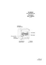
background image

Issue:   6

9

th

 July 2019

BA384NG

Ex nA and Ex tc

Two input

Rate Totaliser

Issue 6

Summary of Contents for BA384NG

Page 1: ...Issue 6 9th July 2019 BA384NG Ex nA and Ex tc Two input Rate Totaliser Issue 6 ...

Page 2: ... count 6 10 Upper display di5p 1 6 11 Lower display di5p 2 6 12 Position of decimal points dp 6 13 Flowmeter K factor factor a 6 14 Total scale factor 5cale t a 6 15 Rate scale factor 5cale r a 6 16 Timebase t ba5e 6 17 Display filter filter a 6 18 Clip off clp off a 6 19 Local reset loc clr 6 20 Local total reset clt tot 6 21 Local grand total reset clr gtot 6 22 External reset e clr 6 23 Grand t...

Page 3: ...tment 5p1r a 11 4 7 Alarm function hi lo 11 4 8 Alarm output status no nc 11 4 9 Hysteresis h5tr 11 4 10 Alarm delay dela 11 4 11 Alarm silence time 5il 11 4 12 Flash display fl5h 11 4 13 Access setpoints ac5p 11 4 14 Adjusting alarm setpoints from totalising mode 11 5 4 20mA output 11 5 1 Ex nA certification 11 5 2 Configuration 11 5 3 Access 4 20mA output sub menu 4 20 op 11 5 4 Enable 4 20mA ou...

Page 4: ...4 ...

Page 5: ...tion which is described in Appendix 3 This instruction manual supplements the abbreviated instruction sheet supplied with each instrument 2 OPERATION Fig 1 shows a simplified block diagram of the BA384NG Rate Totaliser The instrument has two separate inputs A and b which can accept pulses from two flowmeters and display the individual rates and totals or the sum or difference of the two rates and ...

Page 6: ... counter If buttons are pressed for longer than 10 seconds the grand total will be reset to zero if the grand total reset function clr gtot is enabled See 6 21 To reset the grand total to zero from the operating mode press the and buttons for ten seconds until CLr no is displayed Using the or button change the display to Clr YE5 and press which will reset the grand total and restore the original d...

Page 7: ...is received on the input being displayed Appears to rotate continuously when input frequency exceeds 0 5Hz Hold Activated when input frequency annunciator is below the clip off threshold for the input being displayed Reset Activated while the instrument is annunciator being reset Rate Identifies the rate display annunciator Total Identifies the total display Annunciator RTx Retransmitted pulse ann...

Page 8: ...have been certified intrinsically safe Ex ic without Zener barriers or galvanic isolators as shown on the Type Examination Certificate This allows the Rate Totaliser to be adjusted and configured live when installed in Zones 2 When connected to a suitable system the BA384NG Rate Totaliser may be installed in Zone 2 explosive gas air mixture not likely to occur and if it does will only exist for a ...

Page 9: ...ype of input Link Ui Uo Io Switch contact Yes 15V 10 5V 9 2mA Proximity detector Yes 15V 10 5V 9 2mA Open collector Yes 15V 10 5V 9 2mA Magnetic pick off No 30V 1 1V 0 5mA Voltage input low No 30V 1 1V 0 5mA Voltage input high No 30V 1 1V 0 5mA For input A link terminals 3 and 4 For input b link terminals 7 and 8 3 7 Remote reset terminals The BA384NG total display may be reset by connecting the e...

Page 10: ...that terminals 2 6 10 and RS2 are interconnected within the BA384NG See Fig 1 4 1 Power supply The BA384NG Rate Totaliser requires a minimum of 10V between terminal 1 2 and consumes 10mA without optional backlight plus 6mA when terminals 3 4 are linked plus 6mA when terminals 7 8 are linked plus 16mA with optional backlight A 24V dc regulated current limited supply located in a safe area is suitab...

Page 11: ...o determine their state which is achieved by linking two BA384NG terminals together for each input as shown in Figs 3 and 4 Fig 3 BA384NG flowmeters in Zone 2 The flowmeters may also be located in the safe area as shown in Fig 4 Fig 4 BA384NG flowmeters in the safe area 4 2 1 Switch contact input Any Zone 2 certified flowmeter except intrinsically safe instruments with a mechanically or magnetical...

Page 12: ...ction are independently available for each input See section 6 7 4 2 5 Voltage pulse input Two voltage pulse input ranges are independently selectable in the BA384NG Rate Totaliser configuration menu VoLt5 L and VoLt5 H When configured for either of the voltage pulse ranges the Rate Totaliser s input terminals 5 6 and 9 10 may be directly connected to most certified Zone 2 certified flowmeters exc...

Page 13: ...Annunciator activated each time pulse output open collector is on i e Ron is less than 60Ω 3V direct Annunciator continuously activated Fig 5 shows a BA384NG Rate Totaliser installed in Zone 2 with the pulse output connected to a safe area load The pulse output flows through R1 resulting in a voltage output of about 20V in the safe area when the pulse output is activated Fig 5 Retransmitting pulse...

Page 14: ...d is provided in the bottom right hand corner of the back box for interconnecting cable screens The BA384NG Rate Totaliser may be pipe mounted using a BA393G pipe mounting kit 5 2 Installation Procedure Fig 6 illustrates the instrument installation procedure A Remove the Rate Totaliser assembly by unscrewing the four captive A screws B Mount the enclosure back box on a flat surface and secure with...

Page 15: ... the instrument is ordered a blank scale card will be fitted which can easily be marked on site with a dry transfer or a permanent marker Custom printed scale cards are available from BEKA associates as an accessory To remove the scale card from a Rate Totaliser carefully pull the transparent tab at the rear of the instrument assembly away from the assembly as shown in Fig 8a Fig 8a Removing scale...

Page 16: ... Totalisier channel are identified with a suffix i e the rate scale factor 5CALE r A applies to channel A and 5CALE R b applies to channel b Configuration functions that do not have a channel suffix such as the timebase t bA5E apply to both channels The frequency of pulses received at each input is divided by FACtor A or FACtor b which is usually set to the K factor of the flowmeter thus convertin...

Page 17: ...17 ...

Page 18: ...18 ...

Page 19: ...19 ...

Page 20: ... within 60 seconds the instrument will automatically return to the totalising mode and any configuration changes will not be stored When configuring a BA384NG Rate Totaliser it is therefore advisable to occasionally return to the totalising mode to ensure that recent configuration changes are stored in permanent memory 6 3 Summary of configuration functions This section summarises all the configur...

Page 21: ...ACtor A Input A flowmeter K factor Each input of the rate totaliser is divided by FACtor A or factor b which are usually set to the K factor of the flowmeter thus converting the flowmeter output into engineering units FACtor may be adjusted between 0 0001 and 99999 When the 16 segment lineariser Lin is selected in the Function sub menu up to 16 values for FACtor a may be entered each starting at a...

Page 22: ... and buttons are operated simultaneously for more than 3 seconds in the totalising mode See section 6 20 Local grand total reset clr gtot When on is selected grand total may be reset to zero when and buttons are operated simultaneously for more than 10 seconds in the totalising mode Note Once reset the grand total can not be recovered See section 6 21 Display Summary of function e clr External res...

Page 23: ...n menu and press which will reveal the inP tYPE prompt pressing again will reveal the existing input If set as required press twice to return to the configuration menu or repeatedly press the or button until the required type of input is displayed and then press twice to return to the configuration menu One of following six types may be selected for each input Switching thresholds Low High VoLt5 L...

Page 24: ...e required interval has been selected press to enter the selection and return to the configuration menu 6 9 Composite display Count The BA384NG can produce a composite rate and total display from the sum or difference of Input A and Input b This composite display is only meaningful if Input A and Input b are calibrated to have the same engineering units of display This function defines the composi...

Page 25: ...es per litre FACtor A therefore converts the flowmeter output into engineering units ready for further scaling to produce the required rate and total flow displays See Fig 9 When the 16 segment lineariser Lin is selected in FunCtion up to 16 values of FACtor A may be entered each starting at a specified input pulse frequency which may be adjusted to compensate for flowmeter non linearity See secti...

Page 26: ...multiplies the rate display by 1 60 or 3 600 depending upon whether the Rate Totaliser is required to display flow rate per second per minute or per hour See Fig 9 To check or change the timebase select t bA5E from the configuration menu and press which will reveal the existing setting Pressing the or button will scroll through the following three options to display tb 1 for flow second tb 60 for ...

Page 27: ...ay decimal point are changed clip off will automatically be reset to zero A new clip off threshold must be entered after changes to any of these functions have been made 6 19 Local reset LoC clr The Local reset function contains two sub functions clr tot and clr gtot which when enabled allow each input total and the grand total to be reset to zero via the instrument push buttons while the Rate Tot...

Page 28: ...d the button to move control to the next digit When entered pressing will reset the grand total to zero and return the Rate Totaliser to the configuration menu Note Once reset the grand total can not be recovered 6 24 Security code CodE Access to the instrument configuration menu may be protected by a four digit alphanumeric security code which must be entered to gain access Unless otherwise reque...

Page 29: ...Flowmeter specification Flowmeters are usually supplied with a calibration certificate specifying the average K factor and the flow range over which it applies For use over extended flow ranges and for non linear devices multiple K factors will be specified often in a table similar to the one shown below Flow Rate Litres minute K factor Pulse litre 5 200 10 230 15 239 20 242 From this calibration ...

Page 30: ...30 ...

Page 31: ...cted to separate flowmeters with the same non linearity this sub function simplifies configuration by copying input A lineariser configuration to the input b lineariser so that the information only has to be entered once Select FACtor A in the configuration menu and press which will reveal one of five sub functions If Copy A2b is not displayed repeatedly press the or button to select Copy A2b Pres...

Page 32: ...is digit is correct pressing will transfer control to the next digit When the input frequency for this lineariser segment is set as required press the button to return to the segment identification display from which the next segment may be selected using or push buttons When the input frequency for all of the segments has been entered return to the FACtor A prompt in the configuration menu by ope...

Page 33: ...cy of the preceding segment or at an input frequency which is not less than the frequency of the following segment the error message VALuE Err will be displayed To avoid generating an error it may be easier to enter the bottom and top frequencies first and then insert new break points between them 7 9 Lineariser factory defaults The linearisers factory defaults are two breakpoints producing one se...

Page 34: ...it of the composite total display input A input b Note The 5CALEd function is not available when the composite total is input A input b When 5CALEd is selected two additional functions diVidE and durAtion are added to the sub menu allowing the output pulse frequency to be divided and the output pulse width duration to be defined see Fig 13 8 2 Access Pulse output sub menu PuL5E oP Access the Rate ...

Page 35: ...ged by pressing the or push button to select the required value followed by the button to return to diVidE prompt Note This function only appears in the pulse output sub menu when the output pulse is derived from the least significant digit of the composite total display 8 6 Output pulse width durAtion When the output pulse is derived from the least significant digit of the composite total the out...

Page 36: ...the sub menu Again using the or button select inP TYPE and press to reveal the current input The Rate Totaliser is required to work with a magnetic pick off so using the or button select CoiL followed by to return to the inP tYPE prompt in the sub menu Using the or button select dEbouncE from the sub menu and press Using the or button select dEFAuLt which will provide moderate noise protection If ...

Page 37: ...o adjust the flashing digit and the button to transfer control to the next digit and to position the decimal point Finally enter the new figure and return to the FACtor A prompt in the configuration menu by pressing The output from FACtor A will now be in litres which may be scaled to produce required rate and total displays Repeat for input b using the FACtor b function See 6 13 Step 10 Enter the...

Page 38: ... shown on the lower display while the filter parameters are shown and may be adjusted on the upper display Using the or push button select FiLtEr A from the configuration menu and press The first digit which controls the filter time constant will be flashing and should be set to 2 using the or push button The button will transfer control to the second digit which controls the step response and sho...

Page 39: ...the or buttons to set each digit and the button to move control to the next digit Pressing will then reset the composite grand total to zero and return the instrument to the CLr Gtot prompt in the configuration menu See 6 23 Step 17 Define the security code Defining a security code prevents unauthorised access to the configuration menu Using the or buttons select CodE from the configuration menu a...

Page 40: ...ault finding after commissioning EN 60079 17 Electrical installations inspection and maintenance permits live maintenance in Zone 2 if a risk analysis demonstrates that this does not introduce an unacceptable risk The removal of covers opening of Ex n instrument enclosure is permitted if this can be done without contaminating the interior of the instrument with dust or moisture Some end users may ...

Page 41: ...ciates or your local BEKA agent It is helpful if a brief description of the fault symptoms is provided 10 6 Customer comments BEKA is always pleased to receive comments from customers about our products and services All communications are acknowledged and whenever possible suggestions are implemented ...

Page 42: ...ole alarm outputs These may be independently configured as high or low rate or total alarms with normally open or normally closed outputs functioning on input A input b or on the calculated composite rate or total Configurable functions for each alarm include adjustable setpoint alarm delay time and alarm silence time Hysteresis may be applied to rate alarms CAUTION These alarm outputs should not ...

Page 43: ...e fuses and removing the fuses to achieve isolation This is a satisfactory method at the low voltages and currents common in instrumentation systems Clear identification of and easy access to the means of isolation is essential for their effective use It is also necessary to ensure that the maintenance procedure makes sure that unauthorised re closure of the switches does not occur It is not consi...

Page 44: ... See section 11 3 7 no nC Normally open or normally closed output Determines whether the single pole alarm output is open or closed in the non alarm condition See section 11 3 8 H5tr Hysteresis Adjusts the alarm hysteresis Only available on a rate alarm See section 11 3 9 dELA Alarm delay time Adjusts the delay between the display equaling the setpoint and the alarm output being activated See sect...

Page 45: ...45 ...

Page 46: ... and the button to transfer control to the next digit When set as required press to enter the value and return to the setpoint prompt in the alarm sub menu 11 3 7 Alarm function Hi Lo Alarm 1 and Alarm 2 are totally independent both may be Hi or Lo or one may be conditioned as a Hi alarm and the other as a Lo alarm Using the or push button select Hi Lo from the alarm sub menu and press to check or...

Page 47: ...which the alarm has occurred the fla5h function alternates the rate or total display between the numerical value and the alarm identification For example if alarm 1 has been activated by a rate alarm occurring on input A the rate display will alternate between the numerical rate value and AL1 plus the input identification in A if 5td has been selected for the lower display function di5P 2 configur...

Page 48: ...alarm setpoint prompt 5P1r or 5P1t to be displayed If an incorrect security code is entered or a button is not pressed within ten seconds the instrument will automatically return to the totalising mode Once within the menu pressing the or buttons will toggle the display between the two alarm setpoint prompts Fig 17 Setpoint adjustment from the totalising mode To adjust an alarm setpoint select the...

Page 49: ...mply with the requirements of EN 60079 14 Electrical installations design selection and erection each of the wires entering the hazardous area should be individually fused and contain a means of isolation These two requirements may be satisfied by installing DIN rail mounted terminals incorporating a fuse which can easily be opened as shown in Fig 2 to provide isolation Clear identification of and...

Page 50: ...utton select 4 000 in the 4 20mA output sub menu and press which will reveal the existing rate or total display with one digit flashing The required display can be entered using the or push button to adjust the flashing digit and the button to transfer control to the next digit When set as required press to enter the value and return to the 4 000 prompt in the 4 20mA output sub menu 11 4 7 Display...

Page 51: ... tc certificate indicated by the certificate number s X suffix These state that the BA384NG Rate Totaliser should be a Supplied from a limited energy circuit with output parameters in normal operation equal to or less than the instrument s input parameters The certificate states that It is not necessary to power the instrument from an intrinsically safe interface such as a certified shunt diode sa...

Page 52: ...dentical to the ATEX safety parameters described in the main section and Appendix 1 of this manual The IECEx certificate may be downloaded from the BEKA associates or the IECEx website or may be requested from the BEKA sales office A2 2 Installation The IECEx and ATEX certificates specify identical safety parameters and installation requirements for both gas and dust approvals as defined by IEC 60...

Page 53: ...Gc Zone 22 AEx ic tc IIIC T80ºC Dc Ta 40 C to 60 C cETL codes for Canada Ex nA ic IIC T5 Gc Ex n IIC T5 Gc Ex ic tc IIIC T80ºC Dc Class III Div 2 Class II Div 2 Gp F G Ta 40 C to 60 C The ETL and cETL safety parameters are the same as ATEX and IECEx parameters therefore the systems shown in the main section of this manual and in Appendix 1 may be used for US and Canadian installations subject to c...

Reviews: