background image


SB8015A 

All-in-One Bezel Free Android POS Terminal 


User Manual 


User Manual 


Ver 1.0


Summary of Contents for SB8015A

Page 1: ...SB8015A All in One Bezel Free Android POS Terminal User Manual User Manual Ver 1 0...

Page 2: ...nance Chapter 3 Mounting procedures for optional devices such as MSR VFD Chapter 4 5 Motherboard information WARNING Text set off in this manner indicates that failure to follow directions could resul...

Page 3: ...ncouraged to try to correct the interference by one or more of the following measures Reorient or relocate the receiving antenna Increase the separation between the equipment and the receiver Connect...

Page 4: ...is manual contains information protected by copyright No part of this manual may be photocopied or reproduced in any form without prior written consent from the manufacturer The software described in...

Page 5: ...nd for the voltage and current marked on the product s electrical ratings label The voltage and current rating of the cord should be greater than the voltage and current rating marked on the product 1...

Page 6: ...ontents 2 Base System 3 Expandable Options 4 SB8015A Dimensions 5 Connector Panel 6 Chapter 2 Disassemby Guide 7 Detaching the LCD Panel 7 Opening Back Cover 8 Chapter 3 Optional Components and Periph...

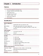
Page 7: ...0 240VAC 50 60Hz 5 0A OS Support Android 4 2 LCD Touch Panel Resolution Size 15 TFT LCD 1024 x 768 Brightness 250 cd m2 Touch Screen Type Bezel Free 5 wire resistive touch I O Ports USB Ports 4 x USB...

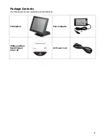
Page 8: ...2 Package Contents The following items come standard with the SB8015A POS System Power Adaptor Utility and Main Board Chipset Driver CD AC Power Cord...

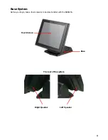
Page 9: ...3 Base System Before you begin take a few moments to become familiar with the SB8015A The rear of the system Right Speaker Left Speaker Touch Screen Base...

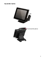
Page 10: ...4 Expandable Options Rear Mount VFD optional...

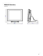
Page 11: ...5 SB8015A Dimensions Unit mm...

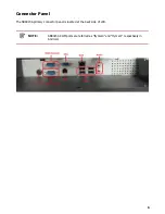
Page 12: ...6 Connector Panel The SB8015A primary connector panel is located at the back side of LCD NOTE SB8015A COM ports are referred as ttymxc0 and ttymxc1 respectively in Android...

Page 13: ...onnect any external devices CAUTION Regardless of the power on state voltage is always present on the main board as long as the system is plugged into an active AC outlet You must disconnect the power...

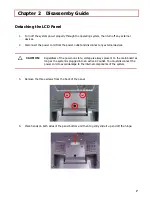
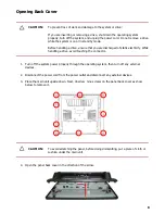
Page 14: ...atic electricity While handling a drive avoid touching the connector 1 Turn off the system power properly through the operating system then turn off any external devices 2 Disconnect the power cord fr...

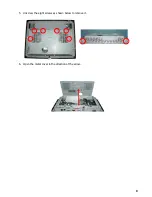
Page 15: ...9 5 Unscrew the eight screws as shown below to remove it 6 Open the metal cover in the direction of the arrow...

Page 16: ...om the power outlet and disconnect any external devices CAUTION Regardless of the power on state voltage is always present on the main board as long as the system is plugged into an active AC outlet Y...

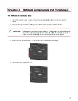
Page 17: ...ut Rear Mount VFD Module Installation 1 Turn off the system power properly through the operating system then turn off any external devices 2 Disconnect the power cord from the power outlet and disconn...

Page 18: ...ord and any external devices then turn on VFD LCD power Finally turn on the system power NOTE The rear mount VFD module is connected with serial interface to Android apps under device name dev ttymxc3...

Page 19: ...13 Chapter 4 Main Board Configuration...

Page 20: ...COM3_SOUT 3 8 NC NC 4 9 COM3_PWR GND 5 COM Connector Pin Definition Pin COM4_PWR COM4 PH_5x2V_2 54mm 2 4 6 8 1 3 5 7 9 COM4_CTS COM4_RTS COM4_SIN COM4_SOUT Pin Pin Definition NC 1 6 NC COM4_SIN 2 7 CO...

Page 21: ...X0 LVDS1_TX0 LVDS1_TX3 LVDS1_CLK LVDS1_CLK LVDS1_TX2 LVDS1_TX2 LVDS1_TX3 C466 100nF VDD_LVDS C467 100nF LVDS1 BB_20x2H_S1 25mm 41 42 43 44 1 3 5 7 9 11 13 15 17 19 21 23 25 27 29 31 33 35 37 39 2 4 6...

Page 22: ...T_PWR1 LVDS_BKLT_POWER Connector Pin Definition Pin VDD_BKLT_LVDS LVDS_BKLT_PWR1 WB_5V_2 0mm 1 2 3 4 5 LCD_BKLT_A LCD_BKLT_PWM_A Pin Pin Definition VDD_BKLT_LVDS 1 4 LCD_BKLT_PWM_A GND 2 5 V5 LCD_BKLT...

Page 23: ...COM4_PWR V5 V12 PS3 MINISMDC110F 16 1 1A B42 30_100MHz 3A COM4_PWR 5V 1 COM4_PWR 2 12V 3 COM_SEL5 COM5 VCC Select Pin Definition Pin C239 10uF 10 _25V COM_SEL5 PH_3x1V_2 00mm 1 2 3 COM5_PWR V5 V12 B48...

Page 24: ...18 SB8015A Bematech 999 S Oyster Bay Rd Building 104 Bethpage NY 11714 USA Tel 1 516 248 0400 Fax 1 516 495 4075...

Reviews: