background image

Summary of Contents for KA 185

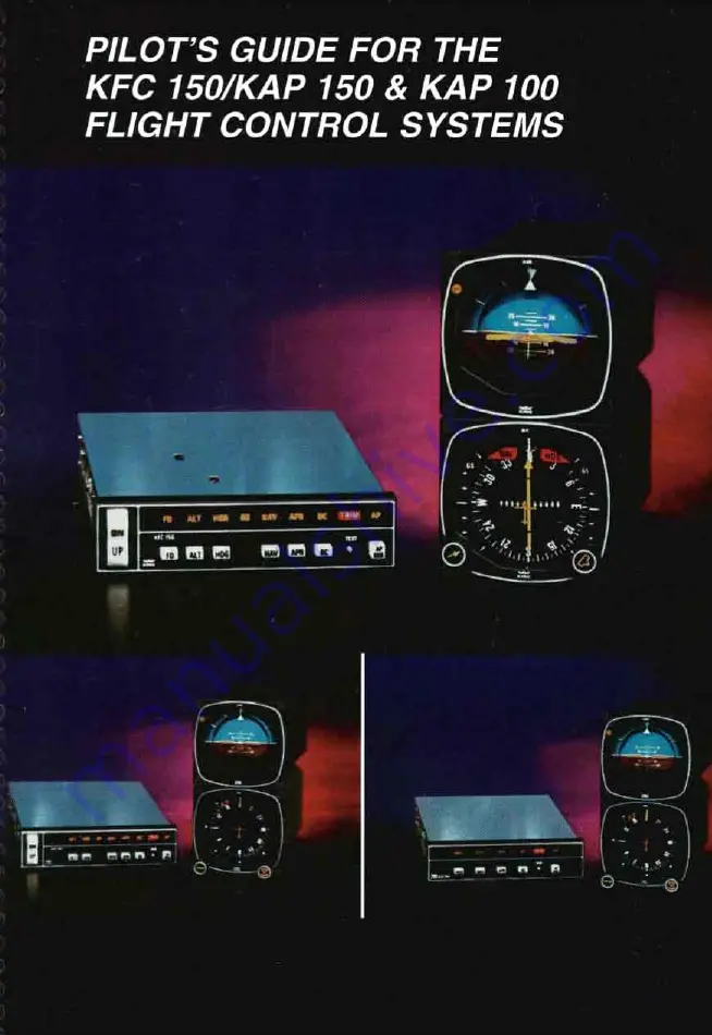
Page 1: ...PILOT S GUIDE FOR THE KFC ISO KAP 150 KAP 100 FLIGHT CONTROL SYSTEMS I__...

Page 2: ...ringMode CWS 23 TakeoffandClimbto AssignedAltitude 24 25 VOR RNAVCapture 30 31 The KAP 150 Autopilot System 33 Modesof Operation 34 35 SystemSelfTest 36 Attitude Referenc of Operation 37 Autopilot Mod...

Page 3: ...G107 KI206 Outboundon FrontCoursefor Proc FrontCourse ILSApproach KG 107 KI206 RNAVCapture KG 107 KI206 RNAVCapture KI525A LongRangeNAVTracking Optional KAS2978 Altitude and Vertical Speed Selector Al...

Page 4: ...also significantthat these Silver Crown flight control systems have been designedfrom the beginningto interface with your Silver Crown package of COMM NAV Pulse products Consider the advantage of hav...

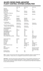
Page 5: ...ontrol System U P 150AutotMot Svstem The M P 150 Autopilot System is a two axis panel mounted digital system which delivers highly sophisticatedIFR capability It has modes and functions simi lar to th...

Page 6: ...Yes Yes Yes Standard Optional Yes Yes Yes Yes Both Yes Yes KAP 150 Yes Optional Standard Standard Standard Standard Optionalfor some aircraft Optionalfor some aircraft Optionalfor some aircraft Yes O...

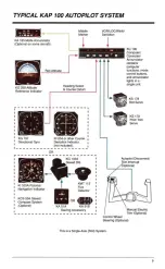
Page 7: ...n the case of the KAP 100 roll commands only In the KFC 150system these commands are rout ed through the KI 256 Flight Command Indicator FCI where they are displayedon the V Bar as visual guidance com...

Page 8: ...Gyro Deviation Indicator I not included I OR KG 102A I 1 L SlavedDG I I I I I I 1 KMT112 I I NavigationIndicator Detector I 7 4 I KI 3 cm ricioriai Flux I I I I R 7 I I KCS55A Slaved I I CompassSystem...

Page 9: ...91 Mode Controller Computer Annunciatorfor the KAP 150 incorporates the functions of a computer mode controller and annunciator lights in a single panel mounted unit The KC 191 annunciates all vertica...

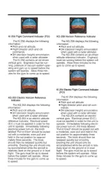
Page 10: ...plied in order for the unit to operate Immediatelyfollowing electrical power turn on the knob labeled Pull to Erect should be pulled out with a moderate even pull and held in the out position for appr...

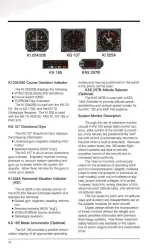
Page 11: ...scan Optional 130A Altimeter to providealtitude prese lectlalertingand vertical speed modes for the KFC 150 and KAP 150 systems System Monitor Description Through the use of extensive monitor circuit...

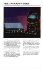
Page 12: ...uding heading hold HDG NAV NAV approach APR and back course BC Likethe KAP 150 the KAP 100 comes equipped with the King KG 107 directional gyro as standard equipment but an option al KCS 55A Compass S...

Page 13: ...7 displays unslavedheading Align headingto magnetic compassby pushingandrotatingthe knobon the lower leftof the KG 107 and update periodicallyto correct for precession Withthe optional KCS55A CompassS...

Page 14: ...will intercept andtrackthe appropriate ILSlocalizeronly V O R or RNAVcourse Withthe front course ILSset onthe CDIor PNI the autopilotwill captureandtracka reverse localizer course BackCourse BC TestBu...

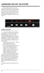
Page 15: ...system is operating normal ly To perform the test momentarily push the test button 1 All annunciator lights the trim light and autopilot light will illuminate 2 The trim light will flash 4 times 3 The...

Page 16: ...gyros have a tendencyto tilt precess to one side If the air supply is reappliedto the gyro while in this state slow gyro erection leveling will occur due to gyro inertia If aircraft operations are ini...

Page 17: ...eadingselect knob If the optional KI 525A is installed set the heading bug on it instead 2 Depressthe HDG buttonon the KC 190 to engage the heading select mode With the autopilot engaged the autopilot...

Page 18: ...with the aircraft level within 4 degrees and within 2 3 dots of course deviation NAV arm mode will be bypassed and the NAV mode will engage directly 4 Within five seconds move the heading bug on the K...

Page 19: ...h the aircraft level within 4 degrees and within 2 3 dots of course deviation NAV arm mode will be bypassedand the NAV mode will engage directly 5 The autopilot will fly the selected headinguntil ente...

Page 20: ...will flash to signify that APR mode is armed NOTE If the APR mode is selected with the aircraft level within 4 degrees and within 2 3 dots of course deviation APR arm mode will be bypassed and the AP...

Page 21: ...he HDG mode 4 Depressthe APR button on the KC 190 APR light will flash to signify that APR mode is armed NOTE If the APR mode is selectedwith the aircraft level within i4degrees and within 2 3 dots of...

Page 22: ...this example The HDG light will remain illuminated and the APR light will flash to signify that the APR mode is armed NOTE If the BC APR mode is selectedwith the aircraft level within 4 degrees and w...

Page 23: ...ill illumi nate 4 Select the back course mode by either depressing the APR buttonand then the BC button or by merely depress ing the BC button itself HDG will remain illuminated BC will illuminate and...

Page 24: ...neuver the aircraft in the roll axis without disengagingthe autopilot To use control wheel steering CWS depress the CWS buttonon the yoke This releasesthe autopilot roll servo and allows you to assume...

Page 25: ......

Page 26: ...0 a 0 0 0 a a 0 a e 0 0 0 a e 0 0 0 0 0 e 0 0 0 0 a 0 0 a 0 a 0 e a a 0 0 0 0 0 0 0 0 e I 1 r 7...

Page 27: ...I 1...

Page 28: ...0 0 0 0 0 0 0 0 0 a 0 0 0 0 0 0 e 0 0 0 0 0 0 1 79...

Page 29: ...80 f...

Page 30: ...C E ti 0 0 I iiii...

Page 31: ...b 1 a2...

Page 32: ...A 83...

Page 33: ...I I I 84...

Page 34: ...85...

Page 35: ......

Page 36: ...L i I m a7 1...

Page 37: ...the course pointer in NAV mode must be rotated to reflect the course or bearingto the new activewaypoint 135 in this case 3 The akraft changes the activewaypoint D via a direct to operation with the L...

Page 38: ...e the autopilot fly informa tion from the Number 2 radio This may be particularlyhelpful if either the Number 1 or Number 2 radio should fail When installedwith a 100 series flight control usingthe KC...

Page 39: ...1 5 1 2812 5 24 85 1 1 27 1 4 1 8 1 2 8 1 4 1 1 1 4 1 3 1 I 4 9 6 I 2811 6 KAP 100 with KG 107 Additional for 3rd axis Additional for Altitude1 yaw damper Vertical Speed Preselect 4 49 2 04 1412 2 2 8...

Page 40: ...the BendidKing Warranty Only these qualified BendidKing Sales Upon completion of your aircraft s flight control installation you will be provid ed with a warranty informationpacket which lists the mo...

Reviews: