background image


berbel- 
Fan Module BLB


Operating and installation instructions for the models: 
BLB 60 FL / BLB 90 FL 
BLB 60 FLE / BLB 90 FLE 


01/2011 (updated 08/2015) 
English translation of the German original manual 

Summary of Contents for BLB 60 FL

Page 1: ...berbel Fan Module BLB Operating and installation instructions for the models BLB 60 FL BLB 90 FL BLB 60 FLE BLB 90 FLE 01 2011 updated 08 2015 English translation of the German original manual ...

Page 2: ...ies for example You can increase the reliability and service life of the equipment and minimise risks by following the instructions in this manual Layout features in the text The text in this manual is laid out in a standard way This helps you to easily distinguish between the various elements Normal text Cross references Lists or ØAction steps Tips contain special information to help you use the ...

Page 3: ...ge to property or the environment 5 General safety instructions 6 Basic safety instructions 6 Safety instructions for the user 6 Safety instructions for the installer 7 Operating instructions 10 Description for the user 10 Possible operating modes 10 Device view with closed lower section 11 Device view with opened lower section 12 Operating 13 Turning on the ventilation function 13 Changing the po...

Page 4: ...3 Remove the bracket 44 Create the installation cut out 44 Installing the device 45 Safety distances are observed 46 Fitting the bracket BLB 60 FL E 46 Fitting the bracket BLB 90 FL E 47 Hang the device 48 Align the device horizontally 49 Secure the lock 49 Only BLB 60 FLE BLB 90 FLE Connect the connection cable of the fan 50 Connecting the wall box and the window contact switch contacts 51 Creati...

Page 5: ...ons and modifications Do not undertake and independent modifications of or conversions to the device Conversions or modifications without the approval of berbel Ablufttechnik GmbH are not permitted Never bridge or bypass the protective equipment found on the device Layout of hazard notices In this manual you will find the following categories of hazard notices DANGER Notices with the word DANGER w...

Page 6: ...pillary trap is fitted and with the lower section closed Make sure that there are no unsupervised children in the vicinity of the device and that they do not play with it Safety instructions for the user Read this chapter carefully before using or cleaning the device ØFollow the warning notices during all activities on the device Avoiding dangers caused by electric shock Do not use the device with...

Page 7: ...de the air flow Make sure that out flowing air is able to flow into the kitchen without impediment Operating over a solid fuel burning fireplace The device may only be used over a fireplace for solid fuels e g a coal burning stove if the fireplace has a sealed cover which cannot be removed Otherwise there is an increased fire risk due to flying sparks the legal and country specific regulations are...

Page 8: ...e legal regulations for gas installations e g in Germany the technical rules for gas installations TRGI Only install the device if it is connected and fused in accordance with the technical data Do not kink or crush the mains cable Do not use the device with a damaged electrical connection cable In the event of a malfunction disconnect the device immediately from the mains The mains plug must be e...

Page 9: ...tive gloves Avoiding the risk of suffocation If the device and an open fireplace which uses air from the room for its oxygen supply gases or waste gases may be drawn into the room Make sure that all of the permits required for operation in your country have been obtained e g the master chimney sweep Make sure that all standards and guidelines for operating the device in your country are observed E...

Page 10: ...erating modes are described in the next sections Extracted air mode The device draws room air in and filters dirt particles out of the air The cleaned air is discharged outside Recirculated air mode The filter filling must be replaced at regular intervals in recirculated air mode The device draws room air in and filters dirt particles out of the air The filter filling in the recirculated air filte...

Page 11: ...n fan module BLB 90 FL Rotary knob on and off switch Lower section Illumination All the following descriptions and illustrations are therefore valid for the berbel fan module BLB 60 FL BLB 60 FLE BLB 90 FL and BLB 90 FLE The berbel fan module BLB 90 FL is mainly shown in the illustrations ...

Page 12: ... section fan module BLB 90 FL Capillary trap Upper section Lower section All the following descriptions and illustrations are therefore valid for the berbel fan module BLB 60 FL BLB 60 FLE BLB 90 FL and BLB 90 FLE The berbel fan module BLB 90 FL is mainly shown in the illustrations ...

Page 13: ...t how to operate all the device functions using this rotary knob in the following sections Turning on the ventilation function WARNING Explosion risk and fire hazard from gas or explosive or flammable gas mixtures in the kitchen when operating electrical equipment If you smell gas or there is a suspicion of flammable gas ØDo not operate or switch on any electrical equipment ØEnsure there is an ade...

Page 14: ... on when you start cooking ØIf you are frying turn the device to its highest power setting Use the run on function in hybrid and recirculated air modes so that the filter used BHF or BUF is dried after the actual cooking process This prevents smells developing and ensures it reaches its maximum service life You can operate the device in four different power levels To turn the device on proceed as ...

Page 15: ...Turning off the ventilation function To turn off the ventilation function proceed as follows ØTurn the rotary knob anti clockwise to the 0 position The rotary knob snaps into each power level The device turns off the ventilation function ...

Page 16: ... up the hob The lighting can be used independently from the fan Turn the lighting on To turn on the lighting proceed as follows ØPress on the rotary knob with a finger The lighting is switched on Turn the lighting off To turn off the lighting proceed as follows ØPress on the rotary knob with a finger The lighting is switched off ...

Page 17: ...ional use After each cooking session See Cleaning with normal soiling on page 17 Daily or heavy use At least every three weeks See Cleaning when heavily soiled on page 18 Cleaning with normal soiling The device is designed to capture foreign particles from the room air that is sucked in and to collect them in a grease tray Proceed as follows to clean the device at normal soiling levels ØTurn off t...

Page 18: ...ows to clean the device at heavy soiling levels Remove the lower section ØTurn off the device ØOpen the lower section by putting the rounded edge downwards ØUse a soft damp cloth or kitchen paper towels for cleaning ØWipe off the upper and lower sections ØGrasp the lower section on its sides with both hands when it is hanging down perpendicularly ØLift the lower section about 2 cm 1 ØRelease the l...

Page 19: ...pper section e g with a damp cloth ØClean the capillary trap e g in the dish washer ØClean the four surfaces of the recess for the capillary trap e g with a damp cloth ØClean the two edges above the recess for the capillary trap e g with a damp cloth After cleaning replace the cleaned and dry parts as follows Insert the capillary trap ØMake sure that the capillary trap is completely dry before re ...

Page 20: ... 2 until it clicks into place ØMake sure that the lower section is fitted correctly The lower section is fitted correctly when you can move it easily Close the lower section ØClose the lower section by pushing it upwards until the two magnetic fasteners can be heard to click together Cleaning the surfaces ATTENTION Damage to the surfaces from sharp objects or abrasive cleaning agents ØNever use sh...

Page 21: ...b can only be attached if the milled sides are turned so they match each other Removing the rotary knob ØPull off the rotary knob Cleaning the rotary knob ØClean the rotary knob in the dishwasher or using a damp cloth Fitting the rotary knob ATTENTION Damage to the rotary knob through misalignment ØTurn the rotary knob around to the correct installation position ØInstall the rotary knob by pushing...

Page 22: ...least every 12 months or when there are odours in the exhaust air WARNING Risk of falling when changing the filter or during work carried out at height ØUse a stable step ladder WARNING Risk of injury from hot parts ØEnsure that the cooking hob and the device have cooled down ØLet all parts cool down before beginning work WARNING Risk of injury from falling parts ØEnsure that no one is beneath the...

Page 23: ...r ØLift the filter at least 3 cm 1 ØRemove the filter to the front 2 The filter is removed Remove the recirculation air filters To change the filter filling proceed as follows ØLift the filter at least 3 cm 1 ØRemove the filter to the front 2 The filter is removed Change the filter filling The method for changing the filter s filling is described separately in an instruction manual for the filter ...

Page 24: ...e fan s housing and the gap is approximately 5 mm wide ØMake sure that the filter is inserted correctly If the filter is not correctly fitted proceed as follows ØRemove the filter ØReplace the filter again Only in hybrid operation ØPush the exhaust pipe onto the filter collar ØSeal the transition between the exhaust pipe and the guide with the help of sealing tape ØEnsure that the exhaust pipe is ...

Page 25: ...it breaker on again For other types of fuse consult a qualified electrician The extractor hood is not switched on Check all possible power levels See Turning on the ventilation function on page 13 The fan does not work The extractor hood is connected to a window contact switch and the window is closed Open the window BLB 60 FLE 90 FLE External fan does not function No power supply or connecting ca...

Page 26: ...rculated air filters on page 22 The hybrid filter is blocked Replace the filter filling of the hybrid filter See Changing the filter filling hybrid and recirculated air filters on page 22 Poor device performance The exhaust pipe was not properly connected or installed Please consult your berbel dealer or berbel customer services ØIf the fault persists please contact your berbel dealer or berbel cu...

Page 27: ... ØMake sure that all safety instructions and regulations are adhered to during installation Installation for recirculated air mode In this installation a BUF recirculated air filter is fitted to the device s fan outlet ØMake sure that the cross section of the ventilation slits in the top structure is more than 300 cm ØMake sure that the air can flow freely out of the device ØEnsure that you can ch...

Page 28: ...to lack of oxygen when the device is operated at the same time as there is an open fire ØIf the device is operated at the same time as devices which work using room air e g gas stove fire places or gas heaters no gases or exhaust gases are drawn into the room ØEnsure there is an adequate supply of fresh air into the dwelling ØMake sure that the legal provisions of the fire regulations FeuV in Germ...

Page 29: ...raction efficiency of an extractor hood greatly Power loss and noise can be created by tightly diverted air in the exhaust pipe To ensure optimum performance of the device you should ensure that when installing the exhaust hose The exhaust hose is as short and direct as possible The room air to be extracted is able to flow freely through the exhaust pipe without turbulence and back pressure The pr...

Page 30: ...ptimised e g berbel bends Use a suitable cross section The minimum cross section for the exhaust pipe for the 125 systems BEH 60 90 and BLB 60 FL 90FL is 125 mm and for the 150 systems all other berbel extractor hoods is 150 mm Every reduction in the exhaust hose causes unwanted air resistance performance reduction and noises Avoid Exhaust pipes of a smaller diameter Sharp edged exhaust flat air d...

Page 31: ... is not larger than the diameter of the roof feed through The roof feed through does not reduce the cross section of the exhaust pipe A sufficiently large condensation trap is integrated into the exhaust pipe that does not reduce the cross section of the exhaust pipe Exhaust pipe through the exterior wall DANGER Fire hazard due to flammable exhaust pipe Running a flammable exhaust pipe through a s...

Page 32: ...wall box s louvred cover are not narrow and thick The slats of the wall box s louvred cover do not hang straight down There is no insect screen fitted in the wall box Insect screens impair the cross section of the exhaust pipe completely ØUse only flow optimised wall boxes e g BMK F L ...

Page 33: ...ly be used in extracted air mode The diameter of the pipe connection for the BLB 60 FL and BLB 90 FL devices is Ø 125 mm The diameter of the pipe connection for the BLB 60 FLE and BLB 90 FLE devices is Ø 150 mm The BLB 60 FLE and BLB 90 FLE devices can also be delivered with a side right or left 150 mm x 80 mm large flat duct connection The device is designed to be installed flush in cupboards The...

Page 34: ... BLB 60 FL Right bracket Fan module BLB 90 FL Left bracket As a option only for BLB 60 FLE and BLB 90 FLE Side flat channel connector 150 mm x 80 mm Only BLB 60 FLE and BLB 90 FLE Connection socket for external fan Fan outlet Mains plug Contact terminals for the window switch and the wall box ...

Page 35: ...ption for the installer Installation instructions 35 Device view from underneath with a closed lower section Fan module BLB 90 FL Lower section Fan module BLB 60 FLE Illumination Rotary knob on and off switch ...

Page 36: ...Description for the installer 36 Installation instructions Device view from underneath with opened lower section Fan module BLB 90 FL Capillary trap Fan module BLB 60 FLE Lower section Upper section ...

Page 37: ...on all poles from the electricity supply after installation Qualifications of personnel Two persons are required to mechanically install the device These technicians must have sufficient craftsman skills and knowledge The required specialist skills include Knowledge of the regulations on safety at work Ability to read technical drawings Experienced in using electrical and mechanical tools Knowledg...

Page 38: ... by improper connection ØWorking on the power supply may only be done by qualified trained electricians adhering to the country specific regulations and standards e g in Germany DIN 57100 VDE 0100 part 701 DANGER Danger for example of a fatal electric shock by faults caused by an inaccessible plug socket ØEnsure that the power plug is freely accessible so that you can easily and simply isolate the...

Page 39: ...installation of the device Prepare the connection cables for wall box and window contact switch You can connect the device to a window contact switch and a berbel wall box e g BMK F The cable clamps are fitted to the device s housing The connection cables should be laid prior to installing the device Wiring diagram for the window contact and the wall box contact ATTENTION You can damage the electr...

Page 40: ... injury from broken glass ØWear protective gloves ØUnpack the device carefully ØDo not touch broken glass ATTENTION Damage to the surfaces from improper unpacking ØCut the packing tape and straps with scissors ØDo not cut into the protective cardboard packaging ATTENTION Scratched surfaces from metallic sharp edged objects e g belt buckles or tools during transport ØTransport the device without an...

Page 41: ...ckaging ØPlace the pars on a level protected surface Check the delivery ØMakes sure that all the parts are complete as described in the following section ØCheck the delivered parts for damage ØIf any parts are damaged or missing contact your berbel dealer or customer services Scope of delivery BLB 60 FL E Fan module BLB 60 FL E Left bracket Right bracket Installation Instructions 6 x screws cross ...

Page 42: ...nly for recirculated air mode Recirculated air filter BUF 125 Wall box BMK F L Remove the parts for installation Prior to installation there are individual components that must be removed or dismantled to be able to safely install the device ØPerform the following steps sequentially ØPlace the device on its back on a flat clean and protected surface The following illustrations show a device that i...

Page 43: ... rounded edge ØGrasp the lower section on its sides with both hands when it is hanging down perpendicularly ØLift the lower section about 2 cm 1 ØLoosen the lower section by pulling it forwards 2 ØRemove the lower section Remove the capillary trap ØGrasp the sides of the capillary trap with both hands ØPull the capillary trap downwards using both hands ...

Page 44: ...place ØPull off both brackets 2 ØLabel the brackets Left and Right Create the installation cut out The installation cut out must have the following dimensions BLB 60 FL BLB 60 FLE BLB 90 FL BLB 90 FLE Width X in mm 540 mm 840 mm Depth Y in mm 338 mm 338 mm Minimum distance Z to the rear wall in mm 15 mm 15 mm You need a saw for this work step e g jigsaw ØProtect all the surfaces of your working ar...

Page 45: ...cient bearing capacity ØOnly use suitable fastening materials The supplied fastening material is only to be used for fastening into a stable cabinet e g 16 mm wooden sheets If there are other installation conditions you can ask your architect for example about alternative fastening methods before installation ØEnsure that the device is correctly suspended ATTENTION Damage caused by falling parts Ø...

Page 46: ... for 16 mm thick base plates The brackets must only be adjusted for thicker base plates The brackets consist of two parts which are screwed together One part of the bracket is fitted with slotted holes You can adjust the bracket to the base plate thickness by sliding it ØLoosen both screws ØAdjust to the required dimension by sliding the upper part of the bracket accordingly ØRe tighten up both sc...

Page 47: ...ogether One part of the bracket is fitted with slotted holes You can adjust the bracket to the base plate thickness by sliding it ØLoosen both screws ØAdjust to the required dimension by sliding the upper part of the bracket accordingly ØRe tighten up both screws ØEnsure that both brackets are correctly adjusted Both bent metal tabs are above and point to the interior of the cabinet ØPlace the rig...

Page 48: ...ut out in a bearing and stable wooden cabinet e g cabinet body ØMake sure that the bearing capacity is sufficient and use appropriate fastening material For this step you do not require any tools ØEnsure that both levers in the side of the capillary trap bay are locked into the rear ØWith two persons lift the device from underneath into the base panel with the installation cut out In the end posit...

Page 49: ...lignment of the device Proceed as follows ØPush the device into the desired position by pushing against the device on the side with your hand Secure the lock For this work step you need a 2 5 mm ball Allen key To secure the lever after installing the device proceed as follows ØTighten the lever using your thumb ØScrew both levers tight with the corresponding screw ...

Page 50: ...ling parts ØProtect areas and devices e g cooled cooking hob underneath the working area against damage e g using a thick piece of cardboard The connection cable must be laid from the external fan to the receptacle on the device Only BLB 60 FLE BLB 90 FLE Receptacle pin assignments The receptacle is wired as follows Receptacle pin no Description 1 Level 1 2 Level 2 3 Level 3 4 Level 4 5 N 6 PE Onl...

Page 51: ...if you connect the control cables with the wrong polarity ØMake sure that you connect the right poles of the control cable ØConnect wire 1 to connector 1 and wire 2 to connector 2 Terminal for the multi function contact F K Terminal for the wall box BMK Control cable Power supply Wall box BMK F Control contact potential free Control box of the berbel extractor hood Terminals for the wall box The t...

Page 52: ...d ØMake sure that the terminals for the wall box are accessible in the extractor hood In the top corner of the control box are the terminals for the window contact switch and the wall box contacts The terminals are labelled with Fensterschalter window switch and BMK or Mauerkasten wall box The terminal pairs are marked with 1 and 2 To connect the control cable proceed as follows ØOpen the screw of...

Page 53: ...itch in the extractor hood The following step describes how the window contact switch is connected For this work step you need a small Phillips screwdriver for the connection terminals in the berbel extractor hood ØLay the window switch s control cable to the device ØMake sure that the terminals for the window contact switch are accessible in the extractor hood In the top corner of the fan box are...

Page 54: ...hanging the filter or during work carried out at height ØUse a stable step ladder CAUTION Risk of injury from falling parts ØEnsure that no one is underneath the device while working ATTENTION Damage caused by falling parts ØProtect areas and devices e g cooled cooking hob underneath the working area against damage e g using a thick piece of cardboard To make sure that the filter are installed cor...

Page 55: ...re that no one is underneath the device while working ATTENTION Damage caused by falling parts ØProtect areas and devices e g cooled cooking hob underneath the working area against damage e g using a thick piece of cardboard ØPush the exhaust pipe firmly into place on the guide on the fan ØSeal the transition between the exhaust pipe and the guide with the help of sealing tape ØEnsure that the exh...

Page 56: ... g cooled cooking hob underneath the working area against damage e g using a thick piece of cardboard To make sure that the filter are installed correctly a guide is fitted to the device s filter seating The filter is inserted correctly when the bottom edge of the filter is parallel to the top edge of the fan s housing and the gap is approximately 5 mm wide ØPlace the hybrid filter onto the guide ...

Page 57: ...r section into the device from below until the guide grooves of the lower section are in front of the device guide pins at the same time ØPress the lower section rearwards into the device 1 ØPull the lower section downwards 2 until it clicks into place ØMake sure that the lower section is fitted correctly The lower section is fitted correctly when you can move it easily Close the lower section ØCl...

Page 58: ...e mains power plug into a power outlet The berbel extractor hood is installed and ready for use Initial cleaning ATTENTION Damage to the surfaces from sharp objects or abrasive cleaning agents ØNever use sharp objects abrasive or aggressive cleaning agents ØUse a soft damp cloth Cleaning the surfaces ØClean the surfaces with a soft damp cloth and a mild household cleaner ØDry the surfaces using a ...

Page 59: ...or this work step you need a small flat head screwdriver a Phillips screwdriver and a 2 5 mm ball Allen key To remove the device proceed as follows ØDisconnect the power supply to the device on all poles ØRemove the mains plug ØRemove the connection cables for the wall box and the multi function contact if fitted Only BLB 60 FLE and BLB 90 FLE ØRemove the connection cable for the fan Only for hybr...

Page 60: ...vironmental considerations in mind and are made from recyclable materials The packing materials can be returned into the raw material cycle after use As a result valuable resources can be saved The outer packaging is made from cardboard The filling materials and layers are of cardboard of polystyrene The protective foils and bags are made of polyethylene ØDispose of the packaging separated into ma...

Page 61: ... If you want to operate the device in conjunction with an external fan the minimum volume flow rates at the fan box outlet must be set Power level 1 min 200 m h Power level 2 min 300 m h Power level 3 min 400 m h Power level 4 min 500 m h Fan module BLB 60 BLB 60 FL BLB 60 FLE BLB 90 FL BLB 90 FLE Width 550 mm 550 mm 850 mm 850 mm Depth 350 mm 350 mm 350 mm 350 mm Height 350 mm 245 mm 350 mm 245 m...

Page 62: ... Thu 08 00 to 17 00 and Fri 08 00 to 14 00 Fax 49 0 5971 80 80 9 10 Internet www berbel de E mail info berbel de Contacting the customer services of the manufacturer You can contact our customer service department in different ways Choose from the following options Telephone 49 0 5971 80 80 9660 Mon to Thu 10 00 to 17 00 CET Fri 10 00 to 14 00 Fax 49 0 5971 80 80 9 650 E mail service berbel de ...

Page 63: ...Contact 63 ...
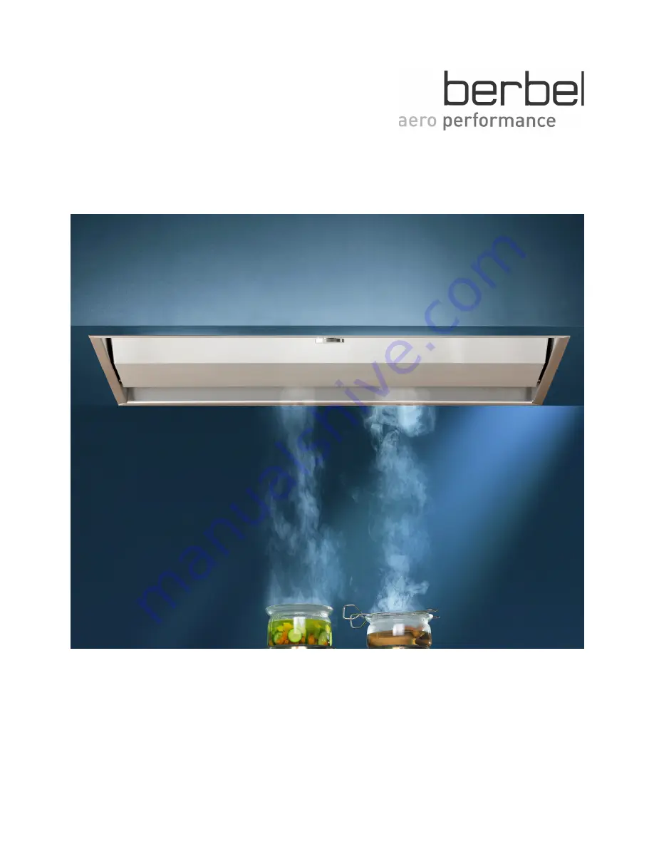
Page 64: ...rman language original manual created by B Gebhardt Büro für Technische Dokumentation 45891 Gelsenkirchen www tddv de Printed in Germany Version 04 08 2015 16 21 6001431 Subject to alterations without notice ...

Reviews: