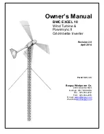
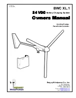
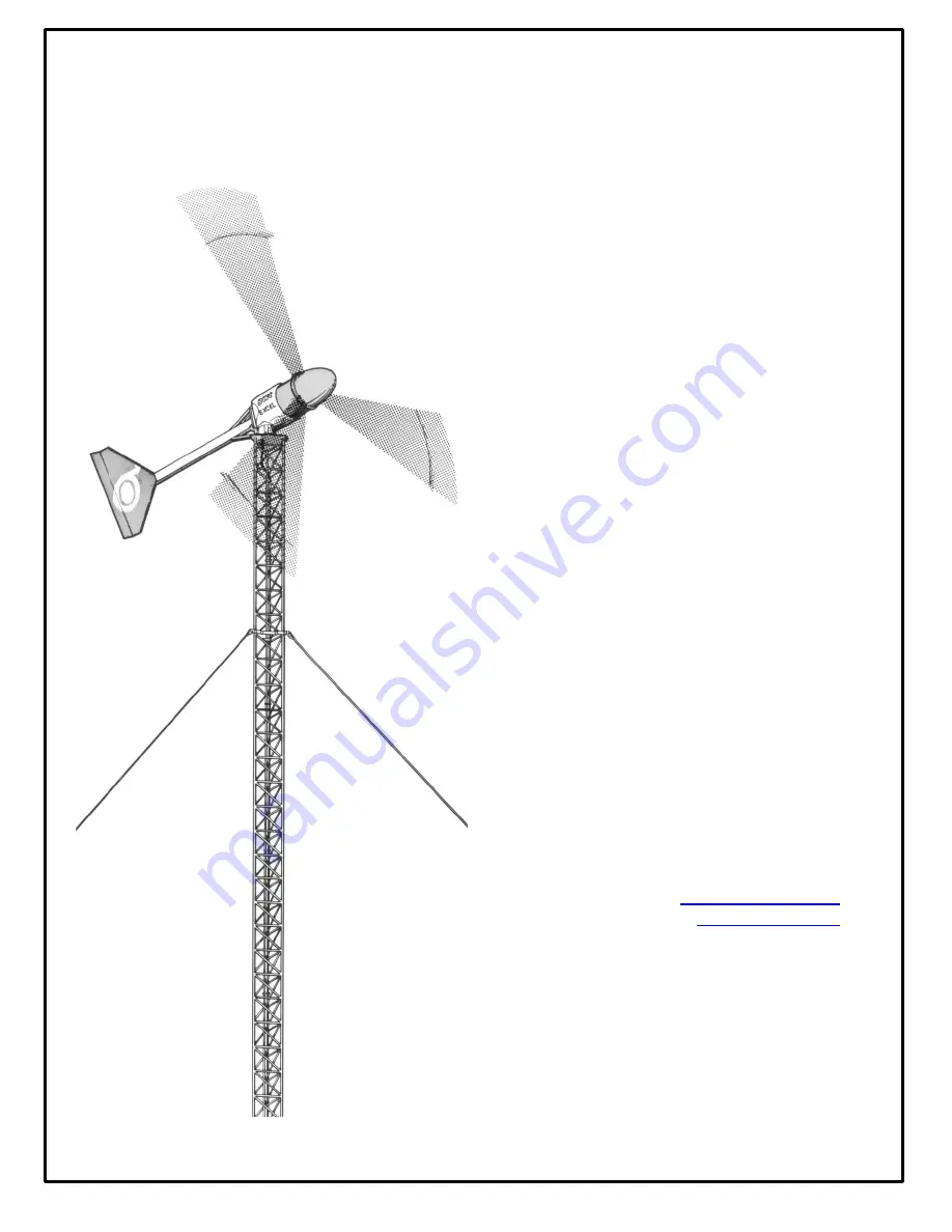
background image


Owner’s Manual 

BWC EXCEL 10 

Wind Turbine & 
Powersync II 
Grid-Intertie Inverter 


Revision 2.0 

April 2014 


Part # 

MANXLS


Bergey Windpower Co. 

2200 Industrial Blvd. 

Norman, OK 73069 USA 

TEL:  405-364-4212 

FAX:  405-364-2078 

E-mail

sales@bergey.com


Web Site:

www.bergey.com


Summary of Contents for BWC EXCEL 10

Page 1: ... Wind Turbine Powersync II Grid Intertie Inverter Revision 2 0 April 2014 Part MANXLS Bergey Windpower Co 2200 Industrial Blvd Norman OK 73069 USA TEL 405 364 4212 FAX 405 364 2078 E mail sales bergey com Web Site www bergey com ...

Page 2: ...OPERATION 9 A NORMAL OPERATION 9 B HIGH WINDS AUTOFURL 10 C UNLOADED OPERATION 10 D MANUAL FURLING 11 E FURLING PROCEDURE 11 V POWERSYNC II INVERTER 13 A INVERTER SPECIFICATIONS 14 B Other Specifications 14 C Important Inverter Safety Instructions 15 D Installation 16 1 Dimensions 16 2 Locating 16 3 Mounting 17 4 Electrical Connections 17 5 AC Output Connection 18 6 AC Input Connection Turbine 18 ...

Page 3: ...creen Display 20 A Inverter Fault Codes 22 VI INSTALLATION 25 A BWC EXCEL WIND TURBINE and TOWER 25 B FUSED DISCONNECT SWITCH 25 C WIRE RUN AND WIRE SIZES 26 D POWERSYNC II INVERTER 26 VII INSPECTIONS AND MAINTENANCE 28 VIII Trouble Shooting Problems 31 ...

Page 4: ...duct damage NOTE Significant points of interest Serial Numbers Each Bergey EXCEL 10 wind turbine has a serial number located on the tower adapter The turbine serial number can also be found on the outside of the shipping crate and on the warranty registration card The blade serial numbers are located on the root pad and also the shipping crate We recommend that the serial number be copied to this ...

Page 5: ...D POWER 10 kW ROTOR SPEED 0 400 RPM MECHANICAL TYPE 3 Blade Upwind Horizontal Axis ROTOR DIAMETER 23 ft 7 0m WEIGHT 1020 lb 460 kg GEARBOX none BLADE PITCH CONTROL none OVERSPEED PROTECTION AUTOFURL TEMPERATURE RANGE 40 to 140 deg F 40 to 60deg C ELECTRICAL OUTPUT FORM 240VAC 1 Phase 60Hz GENERATOR Permanent Magnet Alternator POWER PROCESSOR Powersync II Inverter Power Output AC kW Wind Speed m s ...

Page 6: ... grid on the customer s side of the utility meter The complete unit consists of the following major components as shown in the figure below 1 Spinner 6 Slip ring and Brushes 2 PowerFlex Blades 7 Tail Assembly 3 Alternator 8 Nacelle Assembly 4 Mainframe 9 Furling Winch 5 Yaw Bearing 10 Powersync II Inverter Spinner Nacelle Mainframe Assembly Tail Assembly Rotor Blades Alternator PowersyncII Inverte...

Page 7: ...ity The alternator utilizes permanent magnets and has an inverted configuration in that the outside housing rotates while the internal windings are stationary It was specifically designed for the Bergey EXCEL 10 and produces power at low speeds eliminating the need for a speed increasing gearbox Since it uses permanent magnets the alternator is generating voltage whenever the rotor is turning DANG...

Page 8: ... this actually makes the blades stiffer The AutoFurl system works whether or not the Powersync II inverter is on or not Unlike many other turbines designs the Bergey EXCEL 10 can operate safely without an electrical load connected to the turbine F SPINNER AND NACELLE The spinner nose cone and nacelle provide additional weather protection for the bearings and the slip ring assembly The nacelle also...

Page 9: ...sumer s right to interconnect a wind system and the utilities obligation to purchase excess power are prescribed by federal law PURPA Section 210 The amount you will be credited or paid for this excess production varies state to state and sometimes utility to utility If your utility company offers net metering then your meter is allowed to turn backwards so that you essentially bank energy at full...

Page 10: ...n furled the power output of the turbine will be reduced In winds between 33 mph 15 m s and 45 mph 20 m s it is normal for the turbine to repeatedly furl and then unfurl and then furl again During intermittent cycling the turbine may produce output surges up to 13 000 watts C UNLOADED OPERATION If an abnormal condition occurs on the utility line such as a voltage fluctuation or a complete interrup...

Page 11: ... the cable is tightened the tail folds and the rotor is pulled away form the wind Furling the wind turbine will not stop the rotor completely and it may take some time for the rotor to be pulled around away from the wind Fully furled the rotor will still be partly facing into the wind and will normally turn at a reduced rate The rotor can only be brought to a complete stop by shorting the output l...

Page 12: ...raight normal operation position grasp the winch handle firmly and then release the ratchet mechanism The cable can now be slowly unwound until the turbine has fully straightened out and the cable is slightly slack It is a good idea to then reengage the ratchet DANGER Hold the winch handle firmly before the ratchet is released and until all tension is removed from the cable The winch handle could ...

Page 13: ...he wind turbine into utility compatible power AC The Powersync II inverter has been designed for automatic unattended operation and it is programmed to provide maximum performance from your Bergey EXCEL 10 wind turbine It is also programmed to safely disconnect the wind turbine in the event of a problem with the utility power and to automatically reconnect the turbine after the problem is remedied...

Page 14: ...oltage Range Line Neutral 106 132 VAC Continuous Output Current Maximum 50 Amps Continuous Output Current Tolerance 10 Voltage Measurement Tolerance 10 VAC Operating Frequency Nominal 60 Hz Operating Frequency Range 59 3 to 60 5 Hz Operating Frequency Measurement Tolerance 0 5 Hz Output Power Factor 0 95 0 05 Temperature Range Normal Operation 4 F to 113ºF 20ºC to 45ºC Output Over Current Protecti...

Page 15: ... Use No 4 1 0 AWG 90 C Copper Clad Aluminum or Aluminum Conductors The following symbols are used as markings on this product with the following meanings Equipment grounding conductor This inverter is intended for operation in an indoor NEMA 1 compatible environment having a maximum ambient temperature of 45 C 113 F This unit or system is provided with fixed trip limits and shall not be aggregated...

Page 16: ... a weather protected environment The inverter emits audible noise when operating Do not locate the inverter in living spaces or on walls directly connected to living spaces For maximum energy production avoid installing in direct sunlight or in locations that are likely to exceed 45ºC 113ºF local ambient temperature ...

Page 17: ...ounting feet with 0 281 dia mounting holes For mounting to a 0 10 thick metal surface use M6 20 or 28 bolts grade 3 or higher with nuts and flat washers For mounting to concrete use M6 or bolts using concrete anchors with an 800 pound or greater tension rating The required bolt length is such that the internal threads need to be 100 engaged The enclosure is to be oriented with the conduit openings...

Page 18: ...e delta or wye connection with the neutral not connected to earth ground left floating The inverter must be provided with 3 UL listed fuses rated 400 VAC minimum 50 Amp maximum for proper protection from the wind turbine input to the unit as well as an appropriate UL listed fuse holder to accommodate the fuses Tightening torque allowable wire size and type for the Field Wiring Terminals 50 lbf in ...

Page 19: ...ct box which in turn should be connected to a ground rod at the tower The inverter s earth ground connection must be bonded directly to the service entrance s earth ground which in turn is bonded to neutral Inverter outputs Single phase 208 Vac 6 1 0 AWG 90 C copper wire or 4 1 0 AWG 90 C Aluminum wire 4 AWG minimum recommended Additional disconnect switches may be needed if the inverter is not in...

Page 20: ...cal ambient temperature stays below 45ºC 113ºF If the ventilation is compromised or the heatsink temperature exceeds 60 C the inverter will automatically reduce its output power F Touch Screen Display The touch screen display located on the front panel of the enclosure provides manual over ride and status of the inverter s operation The touch screen display also provides a Stop and a Reset button ...

Page 21: ...lt Displays the last fault that occurred since the inverter was powered up along with a fault code that may be useful when troubleshooting Unit Code Rev Indicates the firmware revision of the control DSP Disp Code Rev Indicates the firmware revision of the LCD display DSP A hidden feature of the display is the contrast adjustment The right side of the display has invisible up and down arrows that ...

Page 22: ...onsumed since it was last calibrated at BWC This measurement is not completely accurate and may not agree with an external meter VREF VREF is the input rectified voltage as a raw value VREF Vdc 2 52 Vref is used as an index look up into a virtual table used for a customizable 32 point power curve table IREF IREF is the current request in counts for a given DC input voltage tracked by VREF Using th...

Page 23: ...ter has been disconnected from the grid It may also occur momentarily when large equipment is turned on nearby TURBINE PHASE 2500 Indicates that there is a problem with one or more of the turbine input phases Bad connection shorted or missing phase When the inverter detects excessive ripple on the DC input it shuts down to protect the turbine from destructive vibration OVER CURRENT 3000 Phase A li...

Page 24: ...rid When a FAULT occurs the Powersync II will shut down no power production and a Fault Code will be displayed on the digital display A list of the Fault Codes can be found in the detailed instructions for the Powersync II inverter provided in the Appendix FAULTS will reset themselves automatically assuming the underlying cause of the fault has been cleared unless the inverter experiences three 3 ...

Page 25: ... ADC switched OFF a shock hazard will still be present inside the Powersync II enclosure for approximately 15 minutes as the capacitor voltage drains down 4 Do not block airflow around the Powersync II enclosure in any way A six inch clearance must be maintained around the sides top and bottom of the enclosure for adequate air circulation VI TURBINE INSTALLATION Please use the following instructio...

Page 26: ...inimum of six inches of clearance is required on the top bottom and sides of the Powersync II to ensure adequate air flow through the enclosure The Powersync II should be connected to a dedicated 70A breaker installed in the main breaker box System grounding is accomplished by attaching a wire 8 AWG minimum from the grounding lug inside the Powersync II enclosure to the panel ground inside the mai...

Page 27: ...CAUTION All loads should be equipped with fuses or circuit breakers to avoid hazards from accidental short circuits 10 kW Wind Turbine 24 m 80 ft GuyedTower Safety Switch Power Processing Unit Inverter Cummulative Production Meter AC Load Center ...

Page 28: ...tor using the procedure given in the installation manuals Climb the tower Always use proper safety climbing gear and safe climbing practices 4 Inspect the blades for A Cracks outboard of the hub pad in the blade pultrusion itself Cracks in the molded hub pad are normal after a few weeks of operation and will not affect the strength or reliability of the blade B Condition of the leading edge protec...

Page 29: ...s C Look for any cracks in the tower structure D Check the condition of the guy wire attachment E Check the furling cable 17 Check the furling winch and make sure that the furling cable is not twisted up If the cable is twisted up check the swivel 18 Check the connection on all ground rods and hardware 19 Remove the alternator shorting connection Check the disconnect switch 20 Switch the disconnec...

Page 30: ... alternate inspection thereafter the right nacelle half should be opened and the slip ring cover removed This will allow the condition of the brushes and slip rings and internal fasteners to be checked DANGER Only qualified personnel with proper safety equipment should climb the tower Never climb the tower when the rotor is turning ...

Page 31: ...ine and then rapidly unwinding the furling cable It should take at least three 3 seconds for the tail to return to the straight position If damper fails the test the turbine should be furled during high winds until the damper is replaced Turbine makes an unusual blade sound such as whistling or buzzing 1 Damaged blade leading edge tape 2 Blade pultrusion structural damage 1 Have leading edge tape ...

Page 32: ...t vibrations in the turbine Sound comes and goes but occurs at the same wind speed s This is normal but contact your dealer or the Bergey Service Department if the noise is excessive Turbine makes a continuous growling or rumbling sound which reduces at higher wind speeds 1 Wiring fault 2 Inverter fault 3 Alternator bearings Switch fused disconnect on tower to OFF If growling disappears an electri...

Page 33: ...nothing ice will dislodge in a few days No need to furl the turbine 2 Contact your dealer 3 Contact your dealer Rotor does not turn at all Mechanical failure inside alternator Rotor does not turn even when winds exceed 15 mph 6 7 m s Contact your dealer Powersync II display not functioning 1 No power to inverter 2 Display or other inverter component not functioning properly 1 Turn off utility powe...

Page 34: ...Owner s Manual BWC EXCEL 10 Turbine Page 34 Appendix ...

Page 35: ...Owner s Manual BWC EXCEL 10 Turbine Page 35 ...

Page 36: ...Owner s Manual BWC EXCEL 10 Turbine Page 36 ...

Page 37: ...Owner s Manual BWC EXCEL 10 Turbine Page 37 Powersync II 240 VAC AMFA 27 and Powersync II 208 VAC AMFA 29 Operator s Manual Installation Instructions Rev 2 6 Date 22 November 2010 ...

Reviews: