
BEST ACCESS SYSTEM
Indianapolis, Indiana
T56145/Rev –
1
Prepare gate
See the installation specifications for 6S gate locks, numbers S09 – S12.
2
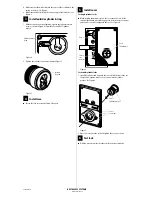
Check handing
1 Unscrew the four case cover screws and lift off the case cover.
2 Check to see if you need to change the handing of the case. See the
figures below.
To change a sliding gate lock handing
1 While compressing the spring on the latch, pull the latch off of the
post. See Figure 2.
2 Turn the latch over and put the latch on the opposite post. See Figure
2.
3 Make sure that the washer fits into the recess of the cradle when the
spring is released. See Figure 2.
4 Position the retractor leg so that it contacts and retracts the latch.
See Figure 2.
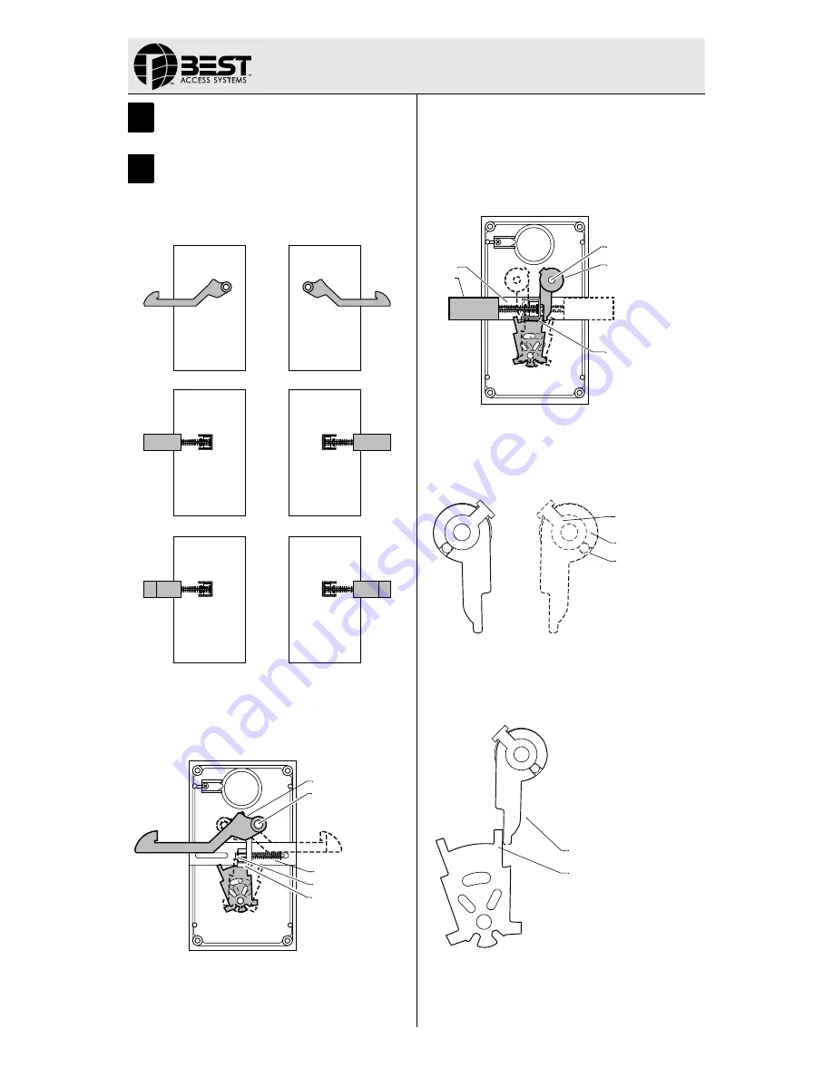
To change swinging gate lock handing
1 Compress the spring on the latch and pull the latch out of the cradle.
See Figure 3.
2 Pull the latch adaptor and latch lever off of the post. See Figure 3.
3 Turn the latch lever over and reengage the latch lever to the latch
adaptor using the same slot. When switched the position should be a
mirror image of the original. See Figure 4.
4 Push the latch adaptor and lever onto the opposite post.
5 Make sure that the latch lever is on the outside of the fork leg. See
Figure 5.
6 Position the latch bevel for the correct swing of the gate.
See Figure 1.
7 Compress the latch spring and place the latch into the cradle.
Figure 1
Figure 2
LH
RH
LH
RH
LHRB
RHRB
Spring
Latch
Post
Washer in cradle
Retractor leg
Figure 3
Figure 4
Figure 5
Spring
Latch adaptor
Post
& latch lever
Latch stop
Latch
Latch lever
Latch adaptor
LH/LHRB
RH/RHRB
Slot
Retractor leg
Latch lever
Installation Instructions
for 6S Gate Locks
T56145/Rev – 18XXXXX ER-7991-19 Nov 2000
1


