background image


1


Robusta SC 


Cantilever sliding 

gates 


Robusta SC 


Installation Manual 

Summary of Contents for R2000

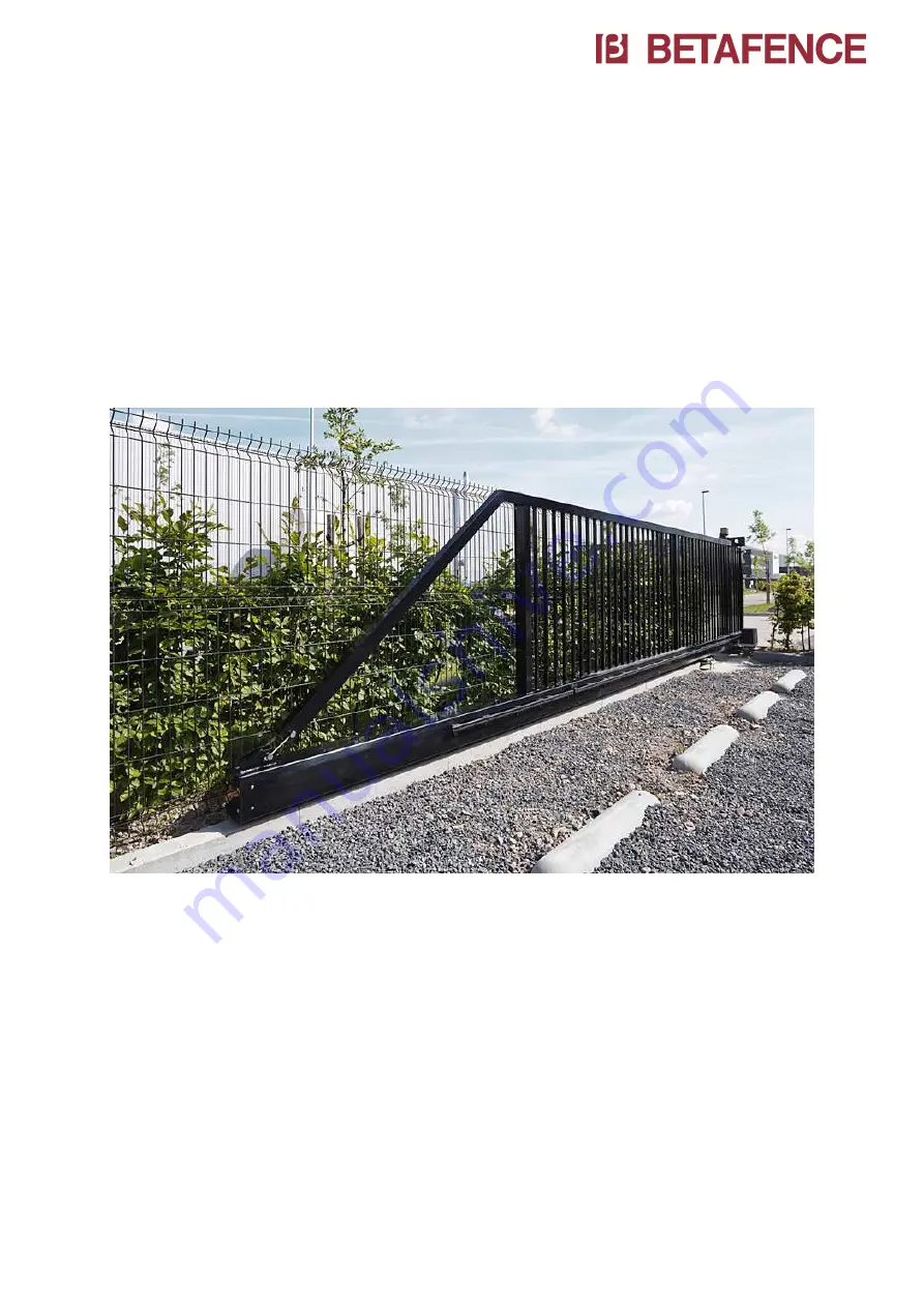
Page 1: ...1 Robusta SC Cantilever sliding gates Robusta SC Installation Manual ...

Page 2: ...otorizable version left opening 14 4 1 5 Manuel version right opening 15 4 1 6 Manuel version left opening 16 4 2 Preparations before gate installation 17 4 3 Installation of the ground anchors 17 4 3 Preparing of the installation levels 18 4 4 Positioning of the gate and posts on the ground anchors 19 4 5 Positioning of the end post onto the ground anchors 21 4 6 Alignment and leveling of the gat...

Page 3: ...eless transmission system for safety strip on the wing 33 9 2 Safety strips 35 9 3 Photocells 36 9 4 Remote controls 36 9 4 1 Programming Remote control devices to the receiver 36 9 4 2 Programming a transmitter to another transmitter 37 10 Overview motorization 38 11 Maintenance 39 12 CE labeling 40 ...

Page 4: ...acturer s instructions The installation regulations can vary from country to country Incorrect installation can cause harm to humans animals and foreign objects for which the manufacturer cannot be held responsible In case of a failure and or poor functioning of the equipment apply exclusively only professional qualified personnel ideally the manufacturer or a certified installer Only original spa...

Page 5: ... can be excluded Reduce speed when reaching the fully open and fully closed positions to avoid unnecessary wear when coming into contact with the buffers Under extreme weather conditions heavy wind hold the wing securely during the opening or closing of the gate so that uncontrolled movement of the wing can be excluded Persons are not allowed to ride on the wing during operation because of the fol...

Page 6: ...er the yearly maintenance it is understood that the maintenance that is described by the manufacturer has been followed If a maintenance contract between the customer and Betafence exists Betafence will carry of this maintenance in cooperation with the user For gates installed in Germany the user must ensure that every 12 months the gate is inspected as per ASR A 1 7 Once inspected the testing age...

Page 7: ...undle The motor included he is mounted on the base plate of the guiding post 2 2 Gate Parts 2 posts guiding post with motor and end post 1 wing with tension system 1 support roll if free passage 5 m Accessories screws nuts limit switch are separately packed in a bag Key of the lock is stuck on the gate see picture ...

Page 8: ...g code o Two pairs of photocells o Two active safety edges at the guiding post o 1 safety edge on front of the wing with wireless system o Completely pre cabled o Warning light o In option gate light Motorizable version o Manual execution with dental rack o Lock post not in line and without lock Manual version o Manuel execution without dental rack o Lock post in line and with lock and catcher Imp...

Page 9: ...points for the unloading and positioning during the Installation The gate may only be lifted with the right equipment for manipulation and sufficient dimensioned for the weight By preference use a type flexible lift ropes with sufficient lifting capacity Lifting points ...

Page 10: ...tions and gate combinations please consult the special foundation drawing supplied with the gate The gate may not be installed following the slope of the construction site Make sure that the foundation for the lock post is at the same level as the foundation for the guiding post Quality of the concrete C25 cubic pressure resistance 25N mm WARNING THE FOUNDATION PLANS ON THE FOLLOWING PAGES ARE ONL...

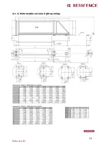
Page 11: ...11 Robusta SC 4 1 1 Automatic version right opening ...

Page 12: ...12 Robusta SC 4 1 2 Automatic version left opening ...

Page 13: ...13 Robusta SC 4 1 3 Motorizable version right opening ...

Page 14: ...14 Robusta SC 4 1 4 Motorizable version left opening ...

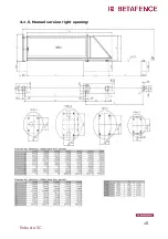
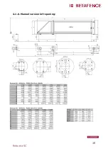
Page 15: ...15 Robusta SC 4 1 5 Manuel version right opening ...

Page 16: ...16 Robusta SC 4 1 6 Manuel version left opening ...

Page 17: ...foundations to indicate the exact position where the gate is to be installed This incorporates the end post the guiding post the rear roller assembly and the rear support roller 2 Install the ground fixations of the guiding and end post according to the positions indicated on the foundation plan Therefore following fixation material is required Chemical anchors M16 minimum 100mm above Finished Gro...

Page 18: ...s some 25mm above the concrete and place the 3D washers onto the nuts 2 Using a spirit level see photo adjust the height of all 4 nuts so that they are horizontal to one and other The guiding post position serves as a reference point for the installation of the other main components Roller assembly lock post and support roller 3 The nuts of each mounting position rear roller assembly and lock post...

Page 19: ... 50 cm above the ground 3 Identify the cables which go to the end post photocells key switch etc 4 Pull these cables through the cable pipe to the lock post 5 Pass the exposed ends of the power supply and other cables through the hole in the base plate of the guiding post and through the hole foreseen into the motor to the connection board ATTENTION Ensure that cables and wires are not crushed bet...

Page 20: ...e ground anchors Put on each ground anchor a washer and a nut Tighten the nuts slightly for temporary fixation Remove straps from the base plate of the guiding post ATTENTION Ensure that cables and wires are not crushed between surfaces while lowering and positioning the gate onto the ground anchors 8 If you have a double wing sliding gate please repeat all steps of point 4 3 and 4 4 for to instal...

Page 21: ...coded connectors together We have provided one or two boxes with connectors for these connections 2 Push the cables back into the tube of the lock post until the connectors are also in the tube This will protect them against water and will facilitate the uninstalling replacement of photocells 3 Position the lock post onto the ground anchors and install the upper washers with nuts Tighten the nuts ...

Page 22: ...BOLTS WHICH SECURE THE ROLLER ASSEMBLY TO THE BASE PLATE 3 Align the rear guiding wheels the guiding post according the gate center line Make sure that the wing is running parallel in the guiding post 4 The guiding post and the rear guiding wheels can be moved laterally in the sleeves of the base plates 5 When the alignment between the rear guiding wheels and the guiding post A is done tighten sli...

Page 23: ... any force on one of the sides when adjusting 5 If you have a double wing gate it is without the lock post and is replaced by a center support plate The installation of the center support bracket must be done as shown in the foundation plan After alignment of the two gates and the horizontal orientation of the wings align the height of the center support plate so that the wheel in front of the win...

Page 24: ...port wheel on the under beam may not force from complete down position on the ramp to enter the lock post 9 After full adjustment of the gate tension up all nuts from the ground anchors Then cut the lengths of the ground anchors 1 2 cm above the nuts and paint afterwards against corrosion 4 8 Installation of the support roll Gates with a free passage more than 5m00 have a support roll for the wing...

Page 25: ... cm from completely open position At this position the support roll may make contact with the underside of the under beam Adjust the height when necessary 4 When you have the correctly height Then tighten we all the M10 nuts for a good fixation of the support roll Important remark Do not adjust the tensioning system Remarks It s very important to fill the space under the plate of the Guiding and l...

Page 26: ...them the front and the rear of the under beam must be opened If the gate is installed correctly according the foundation plan the front end buffer doesn t need to be adjusted as the factory default setting of 60mm will be sufficient However if there is some deviation from the foundation plan or if an obstacle at the rear side of the gate is preventing the wing opening over its full length then adj...

Page 27: ...he rear of the strip and push it into place 6 Now adjust the position of the front detection block when the gate is blocked on its mechanical end buffering in open position 5 2 Adjustment of the rear mechanical end buffer The rear mechanical end buffer is an integral part of the rear roller assembly and is adjustable in length up to 450mm maximum Exception for gates up to 4000mm the adjustable len...

Page 28: ...o that the rubber stop protrudes out of the under beam by 5mm to 10mm Re tighten the counter nut 4 Replace the cover plate to close the under beam and tighten the screws with moderate force 6 Motor height Adjustment 1 Place the wing into the position where it is being supported by both the front and rear roller assemblies 2 Push the lever operated release system see picture into the motor The moto...

Page 29: ...th these screws can you regulate the height of the motor The space between dental wheel and dental rack must be around 1 5 mm Always place the motor on a horizontally level with a spirit level 4 Pull the lever operated release system out the motor Now is the gate in Manuel mode 5 Move the wing over the complete length of movement observing the dental wheel and rack Should meshing problems occur in...

Page 30: ...otor 7 Power Supply Power source must be 230V AC Put the power supply cable into the motor in the hole that is foreseen In the meantime can you also do this with the other cables Connect the power to the correct connector Very important You must make a bridge with earth wire between connector J7 PE and this screw on the motor see picture ...

Page 31: ...ith a section according to the table underneath For example NYJZ 3 x 2 5mm 2 according to VDE0276part 603 VDE 0271 and IEC 52 Section mm2 Maximum distance m 2 5 300 4 600 6 900 WARNING THE CABLE DIAMETER CALCULATIONS ARE BASED ON OUR GATE WITH ALL OUR POSSIBLE ACCESSORIES IF YOU ARE CONNECTING MORE CONSUMERS TO IT IT MAY BE NECESSARY TO USE A BIGGER CROSS SECTION ...

Page 32: ... When the wing goes open right right opening symbol Ǝ Will say Opening limit switch FC 1 Closing limit switch FC 2 When the wing goes open left left opening symbol E Will say Opening limit switch FC 2 Closing limit switch FC 1 Do the settings with parameter d1 in basic function for doing this Example for a right opening When you open the gate in manual mode in the correctly position Fix the limit ...

Page 33: ...es and the automation s control board The radio system comprises of a RB3 R868 radio receiver able to communicate with RB3 T868 transmitters one or two resistive safety edges 8 2 k Ohm XS55 or one of two auxiliary devices N C contacts which can be connected to each transmitter input You can connect on input 1 also an optical safety edge Wiring to FAAC control board 780D equipped at input 6 SAFE on...

Page 34: ...34 Robusta SC TRANSMITTER RB3 T868 Important To ensure a correct function of the system the batteries must be renewed on a yearly basis ...

Page 35: ...ring diagram for the safety edges fitted to the guiding post is presented below With 4 safety strips on the guiding post With two safety strips on the guiding post Check if all safety strips are functioning Two or four safety strips are connected to CN60E module CN60E is connected to the safe input on the control board 780D input 6 ...

Page 36: ...a line of the segment an indication on the display LED FSW CL on board 780D 9 4 Remote controls 9 4 1 Programming Remote control devices to the receiver The gate controller has an one channel receiver connected into the board You can only program one transmitter with the receiver using this direct method Take your 2 channel transmitter and push and hold both buttons 1 and 2 until the led on the to...

Page 37: ... both buttons 2 to 3 secs until the LED on the top starts to flash Release both buttons Transmitter is in programming mode Take the transmitter which is to be programmed and hold it together head to head with the Master transmitter which is already in programming mode see diagram below Push the programmed button on the Master and simultaneous the button to be programmed on the second transmitter W...

Page 38: ...t Two strips on post and two strips on cabinet Type Motorization table Model 500 line 1000 line Underbeam R2000 R2800 Application Normal use 1 Normal use Motor 746 ER16 2 844 ER16 Controller Board 780D 780D Plug in receiver 866MHz 866MHz Nr of transmitters 2 2 photocells XP20W D XP20W D Nr of photocells 2 2 Height photocells 180 900mm 180 900mm Warning Light light 230V LED light 230V LED Safety ed...

Page 39: ...hange broken bolts Check the possible wear of the guiding wheels and clean easy accessible elements Check the opening area of the gate remove all possible obstacles plants snow mud etc Clean the cover of the photocells Check the working of the safety tools safety strips and photocells Check the working of the safety tools safety strips and photocells Only genuine parts will be used for necessary r...

Page 40: ... specified in the EU Construction Products Regulation N 305 2011 and 2006 42 CE A specific Declaration of Performance DoP is available for this gate with number DoP Beta 0xx written on the CE label The contents of this Declaration of Performance can be consulted on the follow link https www betafence com en ce documentation ...

Reviews: