background image

1

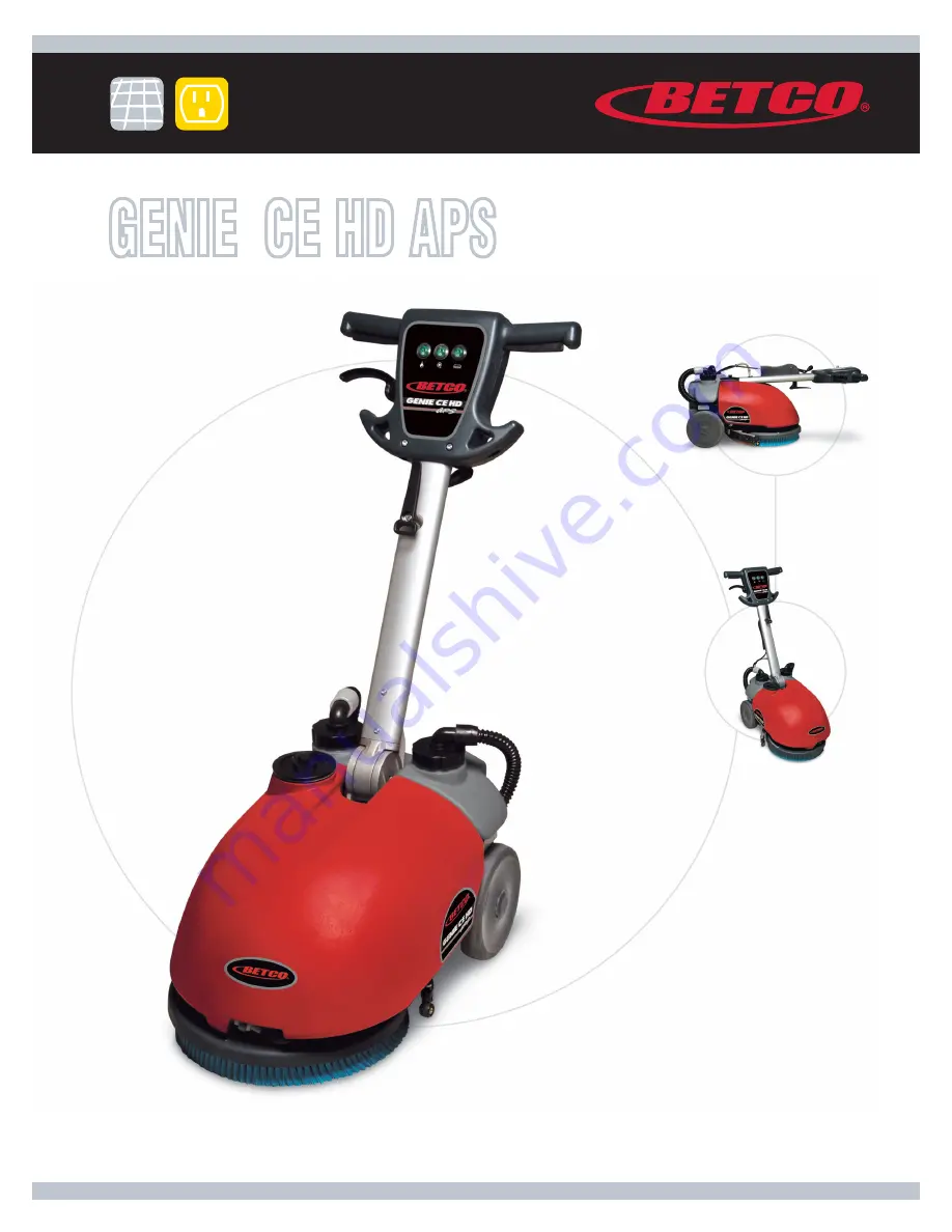
GENIE

 CE HD APS

14” Cord Electric 

Heavy Duty All Purpose 

Automatic Scrubber

E88778-00

1001 Brown Avenue  •  Toledo, Ohio  43607-0127 

Customer Service: 888-GO-BETCO  •  Fax: 800-445-5056  •  Technical Service: 877-856-5954  •  www.betco.com

Operator and Parts 

Manual

Summary of Contents for GENIE CE HD APS

Page 1: ...ord Electric Heavy Duty All Purpose Automatic Scrubber E88778 00 1001 Brown Avenue Toledo Ohio 43607 0127 Customer Service 888 GO BETCO Fax 800 445 5056 Technical Service 877 856 5954 www betco com Operator and Parts Manual ...

Page 2: ...RNING OFF THE MACHINE 10 DAILY MAINTENANCE 11 12 TROUBLESHOOTING 14 BRUSH AND SELECTION USE 15 PARTS DIAGRAMS AND LISTINGS 16 30 TROUBLESHOOTING HANDLE 32 TROUBLESHOOTING WATER SYSTEM 32 TROUBLESHOOTING VACUUM SYSTEM 33 TROUBLESHOOTING BRUSH BASE 34 CHECK LIST 34 MAINTENANCE SCHEDULE AND WEAR ITEMS 35 WARRANTY 36 ...

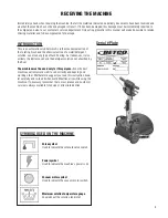
Page 3: ...ooring As it advances it also collects the dirt removed and the detergent solution not absorbed by the floor The machine must be used only for this purpose Even the best machines will only work well if used correctly and kept in good working order We therefore suggest you read this instruction book let carefully and re read it whenever difficulties arise while using the machine If necessary rememb...

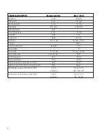
Page 4: ... 2 Vacuum motor V HP V W 115 0 33 115 250 Vacuum Motor Suction in of water mbar 29 72 Solution tank capacity Gal l 2 0 7 5 Recovery tank capacity Gal l 2 5 9 3 Weight of empty machine including brush and tanks lb Kg 77 6 35 2 Weight of empty machine without brush and recovery tank lb Kg 68 6 31 1 Machine dimensions open Length Height Width in x in x in 24 4 x 41 3 x 17 3 mm mm mm 620 1050 440 Mach...

Page 5: ... powder fire extinguisher in case of fire Do not use water Do not hit against shelving or scaffolding The operator must always be equipped with the appropriate safety device gloves shoes helmet glasses etc Do not use the machine on surfaces with an inclination greater than the one shown on the serial plate The machine is designed to wash and dry floors simultaneously Signal the presence of wet flo...

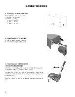
Page 6: ... packing 3 HANDLING AND TRANSPORTATION OF THE UNPACKED MACHINE Genie CE is a machine that can be transported with little effort Be sure that squeegee assembly is in the UP position before transport Lift the front end of the machine using the machine handle as a lever The rear wheels allow it to be transported and can be loaded on a truck with the use of an approved ramp Genie CE is easy to transpo...

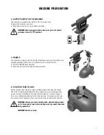
Page 7: ...er upwards B Swing the handle to the upright working position 6 SOLUTION TANK FILLING Fill the solution tank with clean water at a temperature that does not exceed 120 F 50 C Add liquid detergent at the concentration and according to the procedures recommended by the chemical manufacturer To prevent excess foam use a defoaming chemical in the recovery tank If foam passes through the vacuum motor d...

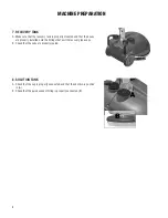
Page 8: ...are properly installed onto the fittings that exit the recovery tank caps B Check that the caps are properly sealed 8 SOLUTION TANK A Check that the cap is properly connected and that the vent pin is pushed in A B Check that the quick connect fitting is properly connected B MACHINE PREPARATION ...

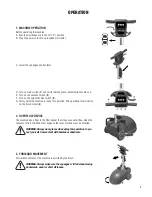
Page 9: ... machine is ready for operation The operating lever will turn on the brush motor 4 2 OVERFLOW DEVICE The machine has a float in the filter basket that stops vacuum airflow when the recovery tank is full When this happens the recovery tank must be emptied WARNING Always wear gloves when doing this operation to pro tect yourself from contact with hazardous chemicals 3 FORWARD MOVEMENT Forward moveme...

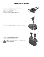
Page 10: ...n off the main switch 1 5 Unplug the power cord from the grounded wall outlet 6 Remove the recovery tank by lifting the rubber latch on top of the recovery tank and pull the tank rearward 7 Remove the recovery tank caps to empty the tank 8 Remove the brush and rinse it with clear water WARNING Always wear gloves to protect yourself from contact with hazardous chemicals TURNING OFF THE MACHINE ...

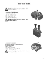
Page 11: ...he tank with clear water WARNING Always wear gloves to protect yourself from contact with hazardous chemicals 2 CLEANING THE SQUEEGEE Verify that the squeegee blades are clean and free from cuts This ensures optimum drying To clean the squeegee A Raise the front of the machine B Carefully clean the inside of the squeegee shoe C Carefully clean the squeegee blades WARNING Always wear gloves to prot...

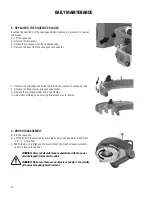
Page 12: ...des G Replace the squeegee blades and band clamps H Reinstall everything by performing this procedures in reverse 4 BRUSH DISASSEMBLY A Lift the squeegee B Lift the front of the machine by pressing down on the handle until the brush is 2 4 off the floor C When the brush is lifted jog the brush motor The brush releases automati cally and falls onto the floor WARNING Carry out all maintenance operat...

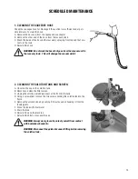
Page 13: ...acuum motor 2 CLEANING THE SOLUTION TANK AND SCREEN A Unscrew the cap on the solution tank B Remove and clean the filter screen C Unplug the solution quick disconnect at the front of the tank D Using a screwdriver remove the two screws holding the solution tank to the frame E Remove the solution tank by pushing it forwards and unhooking it from the locking plate F Rinse the tank with clear water G...

Page 14: ...ater E Verify the vent pin on the solution tank cap is lowered 3 THE MACHINE DOES NOT CLEAN WELL A Check the condition of the brushes or pad Replace them as required Brushes must be replaced when the tufts are roughly 5 8 15 mm long 4 THE SQUEEGEE DOES NOT DRY THE FLOOR A Verify that the squeegee blades are clean B Verify that the vacuum hoses are properly installed and seated on the squeegee C Ve...

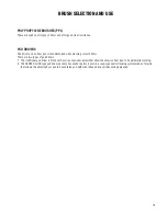
Page 15: ... types of pad drivers 1 The traditional pad driver is fitted with a series of anchor points that allow the abrasive floor pad to be held while working 2 The CENTER LOCK type pad driver not only has anchor points but also a snap type central locking system made of plastic that allows the abrasive floor pad to be centered and held with reduced risk of it becoming detached BRUSH SELECTION AND USE ...

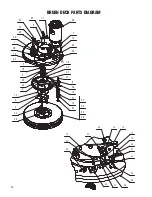
Page 16: ...16 BRUSH DECK PARTS DIAGRAM A 3 2 15 34 8 9 25 16 26 4 16 5 32 24 49 7 12 10 39 29 1 48 12 6 37 11 38 44 36 35 29 22 43 23 47 18 13 20 46 21 31 42 40 41 28 45 33 12 32 24 27 17 30 14 19 48 23 14 ...

Page 17: ...loc Hex Nut M8 Zinc 4 24 E83879 Flat Washer M5x11x1 Zinc 2 25 E20395 Flat Washer M14 SS 1 26 E87290 Shim M37x47x0 3 1 27 E81719 Cap 1 28 E81967 Jam Nut 1 4 NPT Brass 1 29 E81998 Pan Hd Phil Machine Screw M4x10 SS 3 30 E20256 Nyloc Hex Jam Nut M5 Zinc 2 31 E22003 Spacer 3 32 E86250 Hex Bolt M5x14 Zinc 2 33 E81727 Bracket 1 34 E81541 Brush Drive Belt 1 35 E83863 Brush General Scrub 0 3 mm PPL 1 36 E...

Page 18: ...18 SQUEEGEE SYSTEM PARTS DIAGRAM 6 3 4 13 14 12 11 5 18 1 7 10 8 8 18 15 16 5 9 5 17 2 9 ...

Page 19: ...9 Squeegee Blade Rear Shore 33 1 8 E81896 Carriage Bolt M6x16 SS 3 9 E81531 Squeegee Support Wheel 24 OD x 12 7 W 3 10 E81753 Knob M5 6 11 E86264 Carriage Bolt M5x25 SS 2 12 E81941 Carriage Bolt M5x30 SS 2 13 E81815 Squeegee Vacuum Adapter 1 14 E81755 O Ring 1 15 E81909 Front Squeegee Band Clamp 1 16 E82731 Rear Squeegee Blade Band Clamp 1 17 E20616 Carriage Bolt M5 x 35 SS 2 18 E81897 Bushing 3 I...

Page 20: ...20 SQUEEGEE YOKE PARTS DIAGRAM 4 2 11 13 10 6 7 5 2 6 7 9 14 12 8 3 1 ...

Page 21: ...il Machine Screw M5x35 SS 1 6 E83834 Hex Bolt M6x35 Zinc 2 7 E83550 NyLoc Hex Nut M6 Zinc 2 8 E83278 Flat Washer M6 5x24x2 Zinc 1 9 E83710 Cotter Pin D2x20 Zinc 1 10 E83810 Knob 2 11 E86152 Spacer PVC 15x6 5x7 5 1 12 E20382 Nyloc Hex Nut M5 x 5 Zinc 1 13 E81545 Spring 1 14 E88231 Squeegee Lift Cable Genie CE 1 Item Part Description Qty Item Part Description Qty ...

Page 22: ...22 MAIN FRAME PARTS DIAGRAM 4 21 15 32 7 27 33 20 6 2 6 4 6 3 6 1 16 11 34 11 14 24 23 29 12 26 22 19 22 19 31 26 21 18 8 5 2 36 1 9 25 17 28 13 22 12 30 22 19 10 18 35 ...

Page 23: ... Zinc 2 16 E83899 Pan Hd Phil Machine Screw M5x10 SS 2 17 E83535 Hex Nut M5x5 Zinc 1 18 E83550 NyLoc Hex Nut M6 Zinc 3 19 E86853 Nyloc Hex Nut M8 Zinc 6 20 E20251 Flange Nut M8 4 21 E82761 Flat Washer M6x12x1 6 Zinc 3 22 E81874 Flat Washer M8x17x1 6 Zinc 7 23 E86255 Flat Washer M10x21x2 SS 2 24 E83948 Lock Washer M10x18x2 2 Zinc 2 25 E83841 External Serrated Lock Washer M5 Zinc 2 26 E81565 Clamp 4...

Page 24: ...24 SOLUTION AND RECOVERY TANKS PARTS DIAGRAM 10 17 8 19 9 11 19 1 18 12 14 15 5 3 7 20 4 2 13 21 22 6 16 ...

Page 25: ...SS 3 8 E81944 Grommet 1 9 E81849 Vacuum Elbow Fitting 1 10 E81943 Vacuum Elbow Fitting Long 1 11 E86193 Grommet 1 12 E82712 Quick Disconnect Female 1 4 1 13 E81971 Wheel Cap 2 14 E20545 Gasket Vispa 1 15 E88233 Filter Inlet 1 16 E20268 Recovery Tank Vacuum Cap 1 17 E20194 Recovery Tank Inlet Cap 1 18 E20269 Latch Plate 1 19 E20327 Recovery Tank Cap Gasket 2 20 E20307 Magnet 1 21 E20490 Solution Ta...

Page 26: ...26 CONTROL HANDLE PARTS DIAGRAM 35 38 16 26 25 14 40 24 18 31 18 33 37 28 41 27 19 3 44 11 30 29 2 1 3 1 10 34 9 6 12 4 5 32 30 7 18 21 39 42 43 23 22 ...

Page 27: ...773 Flat Washer M10x21x2 Zinc 2 20 E83841 External Serrated Lock Washer M5 Zinc 2 21 E83710 Cotter Pin D2x20 Zinc 1 22 E22014 Circuit Breaker 6A 1 23 E22015 Cord Strain Relief 1 24 E20360 Hex Bolt M6x45 Zinc 1 25 E20364 Button Hd Soc Machine Screw M6x20 Zinc 2 26 E86250 Hex Bolt M5x14 Zinc 1 27 E20567 Bracket 1 28 E81792 Switch Lever 2 29 E81766 Lever Handle Adjustment 1 30 E81994 Support 1 31 E20...

Page 28: ...28 ELECTRIC SYSTEM PARTS DIAGRAM 2 6 4 3 5 3 7 10 2 9 1 8 ...

Page 29: ...ne Screw M6x16 Zinc 2 3 E83550 NyLoc Hex Nut M6 Zinc 2 4 E82761 Flat Washer M6x12x1 6 Zinc 1 5 E22018 Capacitor Start 1 6 E81786 Hose Clip 1 7 E85788 Electrical Housing 1 8 E85771 Electrical Cover 1 9 E88308 Switch Start Run 110V 1 10 E22019 Capacitor Run 1 Item Part Description Qty Item Part Description Qty ...

Page 30: ...30 ELECTRICAL DIAGRAM ...

Page 31: ...31 ...

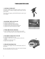
Page 32: ...llow Unscrew the 4 screws which attach the handle support Be sure that the M6x10 screw is loose and that the pin can move Check between the pin and the inside face of the rod that there are 2 to 3 threads 4 VERIFY CLEARANCE BETWEEN THE TIE ROD AND THE LOCKING BOLT If necessary unscrew the M8 nut until there is clearance If the handle bar doesn t lock adjust the lock nut TROUBLE SHOOTING HANDLE 1 C...

Page 33: ...ECT POSITIONING AND THE FUNCTIONALITY OF THE HOSES ON THE CAPS OF THE RECOVERY TANK 3 CHECK THE WEAR OF THE SQUEEGEE BLADE AND THAT THE ATTACHMENT KNOBS ARE TIGHT 4 CHECK THE TIGHTNESS OF THE KNOBS ON THE SQUEEGEE BLADE BAND CLAMP 5 TO ENSURE CORRECT USE OF SQUEEGEE VERIFY FREE MOVEMENT OF SQUEEGEE SUPPORT 1 2 3 4 5 ...

Page 34: ...ck the switches and lights functionality Check the brush base functionality Check the brush motor functionality Check the squeegee functionality Check the vacuum motor functionality Check the condition of the electrical plug and the cables Functional test Fill solution and recovery tanks to check for leaks Check the wear of the squeegee blades Check the functionality of water ball valve and soleno...

Page 35: ...s 250 1 000 Check brush attachments rust ruined parts cracks 250 0 5 2 0 5 s e h s u r b e h t f o r a e w k c e h C BRUSH MOTOR 0 0 1 t e l n i g n i l o o c r i a f o s s e l n a e l c k c e h C 0 0 4 0 5 2 s e h s u r b n o b r a c k c e h C Check Amps consuption and noise level 1 000 VACUUM MOTOR Check noise level and cleanless of the inlet hose 100 0 5 7 0 5 2 s e h s u r b n o b r a c k c e ...

Page 36: ...ts except wear items are warranted by Betco for a period of 3 years Wear Items exempt from Warranty consideration include but may not be limited to power cords transport wheels vacuum bags belts squeegee blades pad drivers clutch plates handle grips filters screens throttle cables brushes and carbon brushes Subject to the conditions and exceptions stated in this warranty Betco warrants the Betco p...

Reviews: