background image


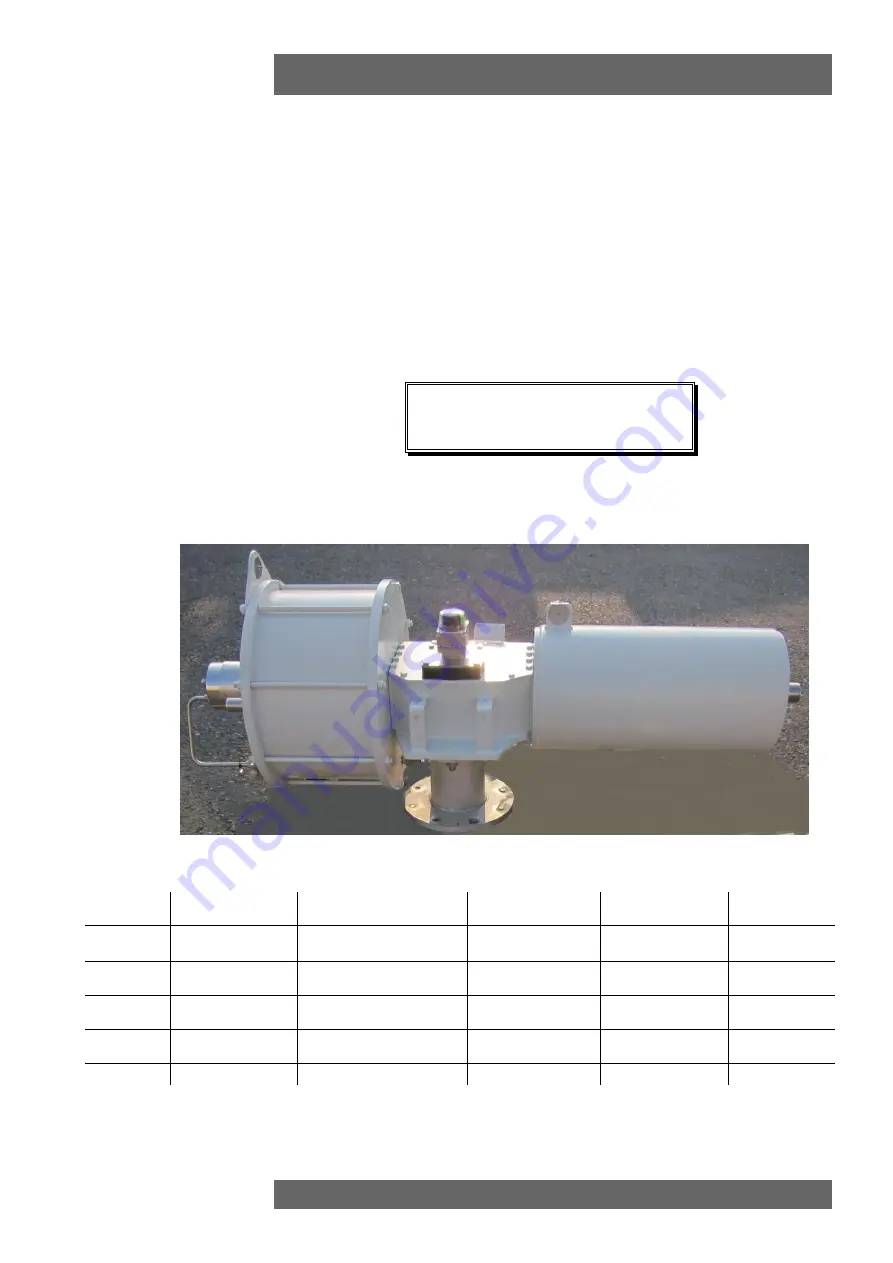
ALGAS-QA  

Instruction and Operation Manual 

© Copyright by BIFFI Italia. All right reserved 

page 1 

Contents may change without notice 

Instruction and Operation Manual 


ALGAS-QA 

“QUICK ACTING” 

SPRING 

RETURN PNEUMATIC 

ACTUATOR 


MAN 616 

21/03/18 

Updated Data-plate 

Ermanni 

Orefici 

Vigliano 

18/04/16 

Updated applicable 

regulation (chapter 1.1.1) 

Ermanni 

Orefici 

Vigliano 

29/03/13 

General update 

Ermanni 

Stoto 

Vigliano 

20/12/05 

Updated document  

Ermanni 

Stoto 

Vigliano 

05/05/99 

Document release 

Lazzarini 

Aliani 

Ziveri 

Rev. 

Date 

Description 

Prepared 

Checked 

Approved 

Summary of Contents for ALGAS-QA Series

Page 1: ...CTING SPRING RETURN PNEUMATIC ACTUATOR MAN 616 4 21 03 18 Updated Data plate Ermanni Orefici Vigliano 3 18 04 16 Updated applicable regulation chapter 1 1 1 Ermanni Orefici Vigliano 2 29 03 13 General update Ermanni Stoto Vigliano 1 20 12 05 Updated document Ermanni Stoto Vigliano 0 05 05 99 Document release Lazzarini Aliani Ziveri Rev Date Description Prepared Checked Approved ...

Page 2: ...ION 19 3 2 RESIDUAL RISKS 20 3 3 OPERATIONS 20 3 4 CALIBRATION OF THE QUICK OPERATION TIME 20 3 4 2 BY PASS ADJUSTMENT 22 3 5 SETTING OF THE ANGULAR STROKE 23 3 6 MICROSWITCHES CALIBRATION APPLICABLE TO BIFFI LIMIT SWITCH BOX MODEL ONLY 28 3 7 PREPARATION FOR START UP 30 3 7 1 Pneumatic connections 30 3 7 2 Electrical connections 30 3 8 START UP 31 4 OPERATIONAL TESTS AND INSPECTIONS 32 5 MAINTENA...

Page 3: ...cumentation contained in this instruction and operating manual Nevertheless Biffi Italia does not provide any guarantees for this instruction manual BIFFI Italia will not be responsible for any mistakes contained in it or for any damage either accidental or due to the use of this manual The information herein contained is reserved property of BIFFI Italia and is subject to being modified without n...

Page 4: ...iffi Italia srl guarantees that all the items produced are free of defects in workmanship and manufacturing materials and meet relevant current specifications provided they are installed used and serviced according to the instructions contained in the present manual The warranty can last either one year from the date of installation by the initial user of the product or eighteen months from the da...

Page 5: ...to bring the valve to the safe position The operating time can be lower than one second depending on the process characteristics valve size and operating pressure The actuator is made up of a weatherproof scotch yoke mechanism transforming the linear movement of the pneumatic cylinder or mechanical manual override if foreseen and of the spring into the rotary movement which is necessary for operat...

Page 6: ...yoke mechanism has a flange with threaded holes to fix the actuator to the valve either directly or if required with the interposition of an adaptor flange or a mounting bracket The actuator yoke has a hole with keyways suitable for the assembly of an insert bush or a stem extension Their internal hole is machined by BIFFI or at Customer s care according to the shape and dimensions of the valve st...

Page 7: ...owledgement and the delivery note 2 2 Storage for handling and lifting procedure please refer to following figures 2 1 2 2 2 3 The actuators leave the factory in excellent working conditions and with an excellent finish these conditions are guaranteed by an individual inspection certificate in order to maintain these characteristics until the actuator is installed on the plant it is necessary to o...

Page 8: ... coupling to the valve the housing is provided with a flange with threaded holes according to Biffi standard tables SCN6200 SCN6200 1 SCN6201 SCN6201 1 The number dimensions and diameter of the holes are made in accordance with ISO 5211 but for actuator models 0 3 to 6 the holes are drilled on the centreline in order to allow an easier assembly of an intermediate flange when required This intermed...

Page 9: ...ALGAS QA Instruction and Operation Manual Copyright by BIFFI Italia All right reserved page 9 Contents may change without notice ...

Page 10: ...ALGAS QA Instruction and Operation Manual Copyright by BIFFI Italia All right reserved page 10 Contents may change without notice ...

Page 11: ... with un machined bore in accordance with Biffi standard table SCN6202 On request the insert bush bore can be machined by Biffi to couple the valve stem provided its dimensions match the maximum stem acceptance of the bush according to Biffi table TN1005 enclosed The particular execution of the flange and bushing allow the actuator to be rotated by 90 in 4 different positions according to the foll...

Page 12: ...nd axis A A from position 2 Rotate insert bush 180 around axis A A from position 1 Insert bush turned upside down Picture 4 Insert bush intermediate coupling flange The Biffi insert bush with 2 external keys at 45 allows to position the keyway for the valve every 90 Consequently actuator can be mounted in 4 positions at 90 on top of the valve For biggest actuator models the bore of the yoke can be...

Page 13: ...ted by means of a suitable lifting apparatus The weight of the actuators is indicated in the technical documentation attached to the equipment itself For lifting and moving the actuator use only hooks fitted with safety latch like the one for example shown in follow figure 2 1 Figure 2 1 Lifting points 1 2 mandatory 3 balancing Lift ALGAS QA actuators pneumatic spring return by means of the proper...

Page 14: ... suspended loads Pay attention in putting under tension the ropes to prevent the load shifting sideways in an uncontrolled manner Use slings of such length that the angles of the leg from vertical are as narrow as possible MAX 20 During handling do not transport the suspended actuator above staff members in charge of the operation DO NOT USE the lifting eyelets on actuator to lift valve actuator a...

Page 15: ...sten it by tightening the proper stop dowels 6 Bring the actuator to the position caused by the spring operation 7 Connect a sling to the support points of the actuator and lift it make sure the sling is suitable for the actuator weight When possible it is easier to assemble the actuator to the valve if the valve stem is in the vertical position In this case the actuator must be lifted while keepi...

Page 16: ...4 550 M27 800 M30 1100 M33 1400 M36 1700 11 If possible operate the actuator to check that it moves the valve smoothly 2 3 3 Valve stem with horizontal axis The actuator can also be lifted to assemble directly onto the valve with stem with horizontal axis To make a correct lifting procedure proceed as follow 1 Connect properly the actuator lifting points 1 with chains and connect by suitable sling...

Page 17: ...ll right reserved page 17 Contents may change without notice 2 Balance the weight and lift the actuator until to make possible the rotation of actuator in its final mounting position with cylinder on top or spring container placed on top as showed in the following images ...

Page 18: ... forcing the coupling When the insert bush has entered the actuator drive sleeve check the holes of the valve flange If they do not meet with the holes of the actuator flange or the stud bolts screwed into them the actuator drive sleeve must be rotated feed the actuator cylinder with air at proper pressure indicated on data sheet for actuator 5 Tighten the nuts of the connecting stud bolts evenly ...

Page 19: ...d through the return line In the second case cutting off or in case of lack of pressure to the cylinder and to the pilot of the fast discharge valve the opening of the latter is determined the fast discharge of motor fluid the quick extension of the spring and the consequent fast operation of the actuator The motor fluid going out from one chamber of the cylinder partially returns in the other cha...

Page 20: ...IONS The operations are carried out sending the proper signal through the control system in compliance with Customer specifications Please refer to the functional diagram and specific documentation supplied 3 4 CALIBRATION OF THE QUICK OPERATION TIME The calibration of the quick operation time of the actuator is carried out through the adjustment of the quick exhaust valve positioned in the tail f...

Page 21: ... Allen wrench and follow these steps Picture 3 4 1 Loosen the locknut Screw with a screwdriver the setting screw to increase the operation time Unscrew with a screwdriver the setting screw to decrease the operation time After the adjustment is over screw the locknut The procedure is absolutely general It is applicable both fail to open and Fail to close actuators Setting screw on quick exhaust val...

Page 22: ... part of cylinder stroke To decrease throttling action turn the needle for by pass in anti clockwise direction To reduce more the operating time higher speed unscrew both By pass screws see diagram in fig 3 4 2 To correctly calibrate the quick operation time it is necessary to arrange the data acquisition using a position transmitter and an ascillographic recorder compatible with required time If ...

Page 23: ...ed by adjusting the travel stop screw on the right side of the actuator 3 5 1 One Travel stop screw screwed on the end flange center of pneumatic cylinder Suitable only for Algas QA models that no need damper action to reduce the operating time in the last part of the cylinder stroke For the adjustment of the travel stop screws proceed as follows see figures A 1 Loosen the lock nut 2 with a proper...

Page 24: ...s A PNEUMATIC CYLINDER SIZE WRENCH C1 mm WRENCH C2 mm 280 17 55 335 17 55 385 17 55 435 17 55 485 17 55 535 17 55 585 17 55 635 17 55 735 17 55 785 17 55 835 17 55 885 17 55 935 17 55 1000 17 55 1100 17 55 1200 17 55 1300 17 80 1450 17 80 PNEUMATIC CYLINDER SIZE WRENCH C1 mm WRENCH C2 mm 85 30 41 100 30 41 135 30 30 175 30 30 235 30 30 ...

Page 25: ...he two travel stop screws in the flange of the pneumatic cylinder proceed as follows see figure C and table A 1 Supply pressure to the cylinder to reduce trust on the stop screws 2 Unscrew the lock nuts d with a proper wrench c2 3 Adjust the travel stop screws g with a proper wrench c1 figure C 4 Rotate anticlockwise to increase the angular stroke rotate clockwise to reduce it 5 Verify that both t...

Page 26: ...ithout notice figure D 6 Reduce or stop cylinder supply to verify the angular stroke 7 Repeat operation until the required angular stroke is attained 8 Tighten the two lock nuts d 3 5 3Stop screw screwed on the end flange of spring container For the adjustment of the travel stop screw proceed as follows see figures B ...

Page 27: ...erated reduce or remove the cylinder pressure in order to move the mechanism far from the screw Operate the setting screw and then pressurize again the cylinder to reach end position 4 If the actuator angular stroke is stopped beyond the end position screw the stop screw by turning it clockwise until the valve reaches the correct position 5 Tighten the lock nut after having correctly placed the th...

Page 28: ... the cover paying attention not to deteriorate the gasket and the cylindrical and flat coupling surfaces Operate the actuator in opening or closing with local pneumatic or hydraulic operation Section 3 3 Unscrew the screw of the operating cam relative to the micro switch to calibrate and adjust it according to the settings Picture 10 Tighten the screw Operate the actuator and adjust any other micr...

Page 29: ...ove the roll pin placed on the position indicator index Turn the indicator until reaching its proper positioning Put the roll pin back in its position End of stroke microswitches should be operated before the stop of the stroke of the actuator due to mechanical stops Adjust the relative cams properly Picture 9 Micro switches box Picture 10 Cam adjustment pin Picture 11 Position indicator and pin f...

Page 30: ...n The ends of the tubes must be well debarred and cleaned Once the connections are completed operate the actuator and check that it functions correctly that the operation times meet the plant requirements and that there are no leaks in the pneumatic connections 3 7 2 Electrical connections Connect the electrical feed control and signal lines to the actuator by linking them up with the terminal blo...

Page 31: ... prescript Check that the feed voltage values of the electric components solenoid valve coils micro switches pressure switches etc are as prescript 2 Check that the actuator controls work properly remote control local control emergency controls etc 3 Check that the required remote signals valve position air pressure etc are correct 4 Check that the setting of the components of the actuator control...

Page 32: ...rried out by qualified staff 5 1 Routine maintenance Algas actuators have been designed to work for long periods in the severest conditions with no need for maintenance Periodicity and regularity of inspections is particularly influenced by specific environmental and working conditions They can be initially determined experimentally and then be improved according to actual maintenance conditions a...

Page 33: ...uator If some areas are damaged repair the paint coat according to the applicable specification 7 Check that there are no leaks in the pneumatic connections If necessary tighten the nuts of the pipe fittings 5 2 Extraordinary maintenance If there are leaks in the hydraulic cylinder pneumatic cylinder or a malfunction in the mechanical components or in case of scheduled preventive maintenance the a...

Page 34: ...n the lock nut 25 and unscrew the stop screws 26 until it is removed from the end flange 22 together with the nuts 25 3 Unscrew the nuts 16 from the tie rods 18 from the side of the end flange they must be gradually unscrewed all at the same time 4 Slide off the end flange 22 and the tube 19 5 2 1 1 Seals replacement Prior to reassemble check that the actuator components are in good conditions and...

Page 35: ...onto the piston taking care not to damage the piston O ring 49 and the head flange O ring 47 2 Assemble the end flange by centering it on the inside diameter of the tube taking care not to damage the O ring 47 3 Assemble the washer 24 and the nuts 16 onto the tie rods 18 Tighten the nuts to the recommended torque alternating between opposite corners 4 Screw the stop screw 26 into the threaded hole...

Page 36: ...ALGAS QA Instruction and Operation Manual Copyright by BIFFI Italia All right reserved page 36 Contents may change without notice ...

Page 37: ...es of the cover after removing the plugs The following grease is used by BIFFI for standard working temperature and suggested for re lubrication AGIP MU EP 2 AEROSHELL GREASE 7 or equivalent To be used in standard temperature conditions 30 C 85 C NLGI consistency 2 Worked penetration 280 dmm ASTM Dropping Point 185 C Base oil viscosity at 40 C 160 mm s ISO Classification L X BCHB 2 DIN 51 825 KP2K...

Page 38: ...s discharged from the cylinder by the linear movement generated from the spring releasing It moves actuator and consequently the valve in hits fail safe position If actuator is still mounted onto the valve loosen the threaded connections between valve and actuator screws tie rods nuts Lift the actuator using the proper lifting points see chapter B pages from 8 to 13 If the actuator needs storage b...

Page 39: ...too slow Low supply pressure Restore Sect 1 4 Wrong calibration of flow regulator valves Restore Sect 3 6 Bad functioning of quick exhaust valve Call BIFFI Italia S r l Customer Service Wear of the valve Replace Actuator too fast High supply pressure Restore Sect 1 4 Bad functioning of booster quick exhaust valve Call BIFFI Italia S r l Customer Service Wrong calibration of flow regulator valves R...

Page 40: ...and Operation Manual Copyright by BIFFI Italia All right reserved page 40 Contents may change without notice 7 LAYOUTS SECTIONAL DRAWINGS 7 1 Parts list for maintenance and replacing procedure Table 1 Scotch yoke mechanism ...

Page 41: ...ALGAS QA Instruction and Operation Manual Copyright by BIFFI Italia All right reserved page 41 Contents may change without notice Table 2 pneumatic cylinder ...

Page 42: ...ALGAS QA Instruction and Operation Manual Copyright by BIFFI Italia All right reserved page 42 Contents may change without notice Table 3 Spring cartridge ...

Page 43: ...ALGAS QA Instruction and Operation Manual Copyright by BIFFI Italia All right reserved page 43 Contents may change without notice Table 4 assembly kit ...

Page 44: ...ALGAS QA Instruction and Operation Manual Copyright by BIFFI Italia All right reserved page 44 Contents may change without notice Table 5 Quick exhaust valve ...

Page 45: ...to BIFFI order confirmation concerning all the supply and serial number of the actuator Section 1 2 for any specific spare part for a specific actuator model Please send every spare parts request to BIFFI ITALIA s r l Spares Office Tel 0523 944523 Fax 0523 941885 E mail spareservice biffi it Please specify 1 Actuator model 2 BIFFI acknowledgement 3 Spare parts code 4 Quantity 5 Transport condition...

Page 46: ...ht reserved page 46 Contents may change without notice 9 Date report for maintenance operations Last maintenance operation date in factory on delivery exec by exec by exec by Next maintenance operation date exec by exec by exec by Start up date in factory on delivery on plant ...

Reviews: