Model 2001SS Spray Gun
OPERATION AND MAINTENANCE INSTRUCTIONS
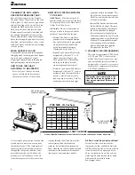
CONTROLLING THE FAN SPRAY:
The fan spray for an external mix nozzle
set-up is easily controlled by means of
the Side Port Control 54-3347. Turning
this control to the right, or clockwise,
until it is closed will give a round spray;
turning it to the left, or counterclockwise,
will widen the spray into a fan shape of
any width desired. The direction of the
fan spray, either horizontal or vertical, is
obtained by turning the air nozzle to the
desired position, then tightening the
retainer ring.
CONTROLLING THE FLUID:
If a fluid
pressure tank is used, the amount of fluid
can be controlled by regulating the
pressure on the tank. The amount of fluid
can also be controlled by means of the
Fluid Control 54-1007. Turning this screw
to the right, or clockwise, reduces the
amount of fluid; to the left, or counter-
clockwise, increases the amount of fluid.
FAULTY SPRAY:
A faulty spray is
caused by improper cleaning or dried
material around the fluid nozzle tip or in
the air nozzle. Soak these parts in a sol-
vent that will soften the dried material
and remove with a brush or cloth. Never
use metal instruments to clean the air or
fluid nozzles. These parts are carefully
machined and any damage to them will
cause a faulty spray. If either the air
nozzle or fluid nozzle is damaged, the
part must be replaced before a perfect
spray can be obtained.
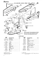
TO REPLACE THE FLUID PACKING:
Remove the Fluid Control Screw 54-1007,
Spring 54-1347 and needle. Then remove
the Fluid Packing Nut 56-164 and take
out the old packing with a small stiff
wire. Replace with new Packing 2-28.
To set packing, insert needle, tighten nut
until the needle begins to be too stiff for
the spring to move needle. Then loosen
nut 1/2 to 3/4 turn.
CORRECTING AIR LEAK
THROUGH GUN:
Air leaking through
the gun is caused by the Valve Stem
Assembly 54-1025, not seating properly
against the Valve Body 54-1010.
Remove the Valve Body 54-1010 and
Valve Stem Assembly 54-1025.
Thoroughly clean parts and inspect for
damage. Replace worn or damaged parts
and assemble in reverse order.
CORRECTING AIR LEAK AROUND
AIR VALVE STEM:
Air leaking around
the Air Valve Stem 54-1025 may be caused
by worn Packings 8-158 or damaged
Air Valve Stem 54-1025. Remove Trigger
54-1050, Packing Nut 82-135 and Packings
82-158. Clean extended portion of
Air Valve Stem 54-1025 and inspect
for damage; if stem is damaged, replace
same as above, insert new packings and
assemble in reverse order.
(Order Separately)
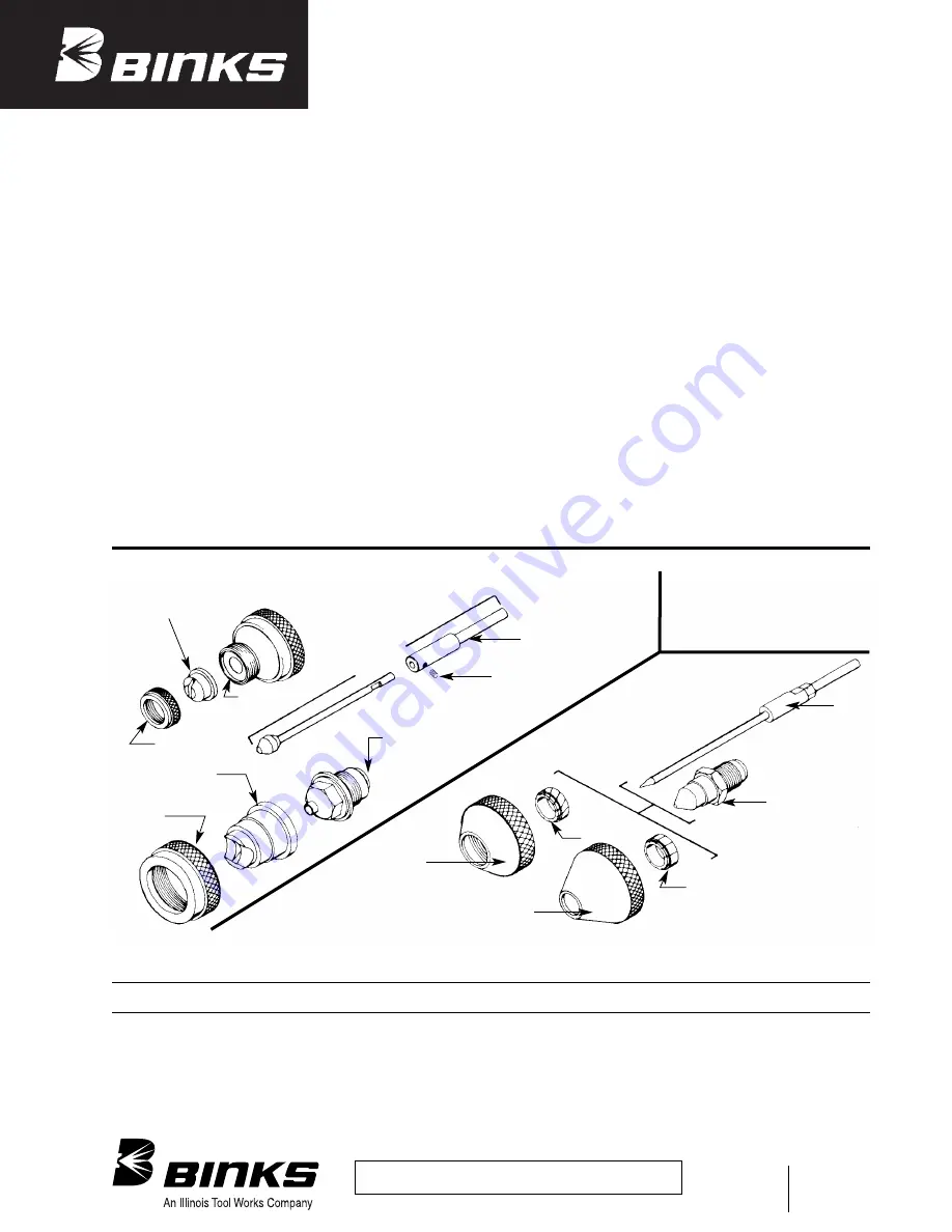
SPECIAL NOZZLES
SPECIAL EFFECT NOZZLES
FLUID NOZZLE
(See Chart)
#794 FLUID NOZZLE
#590
NEEDLE
VALVE
VEILING
DISTRESSING
AIR NOZZLE
(See Chart)
#797 AIR NOZZLE
#793
AIR NOZZLE
#54-2065
RING
#790
CORE
#792
SPIRAL
CORE
#54-1583
BASE
#559 NEEDLE
ASSEMBLY
#54-1227 GUIDE
#54-1584 RING
*NOZZLE TIP:
200 SERIES, NITRALLOY
#20-2093 SCREW
INTERNAL MIX HEAVY MATERIAL
Replaces
Part Sheet
2354R-3
Part
Sheet
77-2354R-4
6/05 © 2005 Illinois Tool Works Inc. All rights reserved. Printed in U.S.A.
ITW Industrial Finishing
Binks has authorized distributors throughout the world. For technical
assistance or the distributor nearest you, see listing below.
U.S./Canada Technical Service Office:
195 Internationale Blvd., Glendale Heights, IL 60139
Toll-Free Telephone: 1-888-992-4657 (U.S.A. and Canada only)
Toll-Free Fax: 1-888-246-5732
ITW Automotive Refinishing
Binks has authorized distributors throughout the world.
For equipment, parts and service, check the Yellow Pages
under “Automotive Body Shop Equipment and Supplies.”
For technical assistance, see listing below.
U.S./Canada Customer Service Office:
1724 Indian Wood Circle, Suite J-K, Maumee, OH 43537
Toll-Free Telephone: 1-800-445-3988 (U.S.A. and Canada only)
Toll-Free Fax: 1-800-445-6643
2354R-4 Revisions:
Changes made to text and illustrations related
to new 1-piece fluid needle design.
Binks Worldwide Sales and Service Listing: www.binks.com
WARRANTY
This product is covered by Binks’ 1 Year Limited Warranty.


