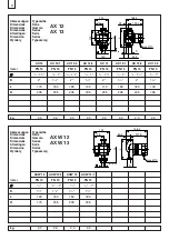
background image

AX 12, AX 13
AXW 12, AXW 13

Biral Umwälzpumpen

Montage- und Betriebsanleitung
Seite 5

Circulateurs Biral

Instructions d’installation et d’entretien
Page 19

Pompe di circolazione Biral

Istruzioni di installazione e funzionamento
Pagina 33

Biral Circulation Pumps

Installation and Operating Instructions
Page 47

Biral circulatiepompen

Montage- en bedrijfsinstructies
Pagina 61

Bombas de circulación Biral

Instrucciones de instalación y funcionamiento
Página 75

Pompy cyrkulacyjne Biral

Instrukcja montażu i eksploatacji
Strona 89

Summary of Contents for AX 12

Page 1: ... circolazione Biral Istruzioni di installazione e funzionamento Pagina 33 Biral Circulation Pumps Installation and Operating Instructions Page 47 Biral circulatiepompen Montage en bedrijfsinstructies Pagina 61 Bombas de circulación Biral Instrucciones de instalación y funcionamiento Página 75 Pompy cyrkulacyjne Biral Instrukcja montażu i eksploatacji Strona 89 ...

Page 2: ...e 2006 95 CE Norme EN 60335 1 EN 60335 2 51 Compatibilità elettromagnetica 2004 108 CE Norme EN 61000 6 2 EN 61000 6 3 Declaration of Conformity EN We Biral AG declare under our sole responsibility that the products AX 12 AX 13 AXW 12 AXW 13 to which this declaration relates are in conformity with the Council Directives on the approximation of the laws of the EC Member States relating to Machinery...

Page 3: ...Staten betreffende Maschines 2006 42 EG Normen EN 12100 1 Elektrisch materiaal bestemd voor gebruik binnen bepaalde spanningsgrenzen 2006 95 EG Normen EN 60335 1 EN 60335 2 51 Elektromagnetische compatibiliteit 2004 108 EG Normen EN 61000 6 2 EN 61000 6 3 Münsingen 1st January 2011 Biral AG Südstrasse 10 CH 3110 Münsingen Phone 41 0 31 720 90 00 Fax 41 0 31 720 94 42 Mail info biral ch www biral c...

Page 4: ...mma Dimensions Series Afmetingen Serie Dimension Series Wymiary Typoszereg AX 12 AX 13 kg 2 3 2 3 2 3 2 3 2 3 2 3 2 3 2 3 78 124 H 140 140 961156_00 L 29 129 4 158 4 D 50 2 max Ø10 AXW 12 AXW 12 1 AXW 13 AXW 13 1 mm PN 10 PN 10 PN 10 PN 10 3 4 3 4 1 3 4 3 4 1 D 11 4 11 2 11 4 11 2 L 120 180 150 180 H 170 235 200 235 Abmessungen Typenreihe Dimensions Série Dimensioni Gamma Dimensions Series Afmetin...

Page 5: ...ur Betriebsdruck 8 4 Montage 8 4 1 Durchspülen der Heizungsanlage 8 4 2 Frostschutzmittel sofern erforderlich 8 4 3 Einbau 8 4 4 Montageposition 9 4 5 Rückschlagventil 9 4 6 Mindestdruck 9 5 Elektrischer Anschluss 10 5 1 Anschlussklemmen 11 5 2 Anschlussschema Standardausführung 11 6 Einstellungen 12 6 1 Einstellung der Regelungsart und Förderhöhe 12 6 2 Werkseitige Einstellung der Pumpe 13 6 3 Re...

Page 6: ...uch die unter den anderen Abschnitten ein gefügten speziellen Sicherheitshinweise 1 2 Kennzeichnung von Hinweisen Dieses Symbol finden Sie bei Sicherheits hinweisen deren Nichtbeachtung Gefahren für die Maschine und deren Funktionen hervorrufen kann Achtung Direkt an der Anlage angebrachte Hinweise wie zum Beispiel Drehrichtungspfeil Kennzeichen für Fluidanschlüsse müssen unbedingt beachtet und in...

Page 7: ...rtem Fachpersonal ausgeführt werden das sich durch eingehendes Studium der Montage und Betriebsanleitung aus reichend informiert hat Grundsätzlich sind arbeiten an der Anlage nur im Stillstand durchzuführen Unmittelbar nach Abschluss der Arbeiten müssen alle Sicherheits und Schutzeinrichtungen wieder angebracht bzw in Funktion gesetzt werden Vor der Wiederinbetriebnahme sind die im Abschnitt Elekt...

Page 8: ...nsgefäss bzw Sicherheitsvorlauf 4 2 Frostschutzmittel sofern erforderlich Wichtig Spülen Sie das Leitungsnetz besonders gut durch bevor das Frostschutz Gemisch eingefüllt wird Befolgen Sie die Anweisungen des Frostschutzlieferanten in Bezug auf Mischen und Einfüllen sowie Materialwahl im Leitungs und Apparatenetz Korrosionsschutz beachten Wasser Glykol Gemisch bis 50 Glykolanteil zulässig Ab 10 Gl...

Page 9: ...ie Durch flussrichtung an Die Welle muss immer waagrecht sein nie senkrecht 4 5 Rückschlagventil Falls ein Rückschlagventil montiert ist muss die Pumpe so eingestellt werden siehe Punkt 5 4 2 dass der minimale Förderdruck der Pumpe jederzeit den Schliessdruck des Ventils übersteigt Absperrschieber vor und nach der Pumpe einbauen Damit wird bei einem möglichen Austausch der Pumpe ein Ablassen und W...

Page 10: ...t Vorsicherung Nennstrom 1 5 max 10 A träge Drahtquerschnitt max 1 5 mm2 Der elektrische Anschluss hat gemäss Datenschild zu erfolgen Für spätere einfache Auswechslung ist der elektrische Anschluss zu schlaufen Eine beschädigte Netzanschlussleitung muss ersetzt werden Es muss darauf geachtet werden dass die elektrischen Daten auf dem Typenschild der Pumpe mit der gegebenen Stromversorgung übereins...

Page 11: ...en Ladestromimpuls gegen Erde berücksichtigen und die für den Ableitstrom kleiner 3 5 mA der Pumpe geeignet sind Die FI Schalter müssen mit dem gezeigten Symbol gekennzeichnet sein Bemerkung Vor jedem Eingriff in den Klemmenkasten der Pumpe muss die Versorgungsspannung abgeschaltet werden Bei falschem Anschluss und falscher Spannung kann die Elektronik beschädigt werden 5 1 Anschlussklemmen deutsc...

Page 12: ...uss über eine Regelung der Mediumtemperatur verfügen 1 Bedientaste 2 Geregelter Betrieb Proportionaldruck pp Sinnvoll in folgenden Anlagen Zweirohrsystemen mit thermischen Ventilen und langen Leitungsstrecken Ventilen mit grossem Arbeitsbereich Hohem Druckverlust Primärkreispumpen mit hohem Druckverlust 3 Geregelter Betrieb Konstantdruck cp Sinnvoll in folgenden Anlagen Zweirohrsystemen mit thermi...

Page 13: ...5 2 2 5 3 3 5 4 4 5 5 m h 6 0 2 0 4 0 6 0 8 1 0 1 2 l s 1 6 v 1 0 5 1 1 5 2 2 5 2 4 6 8 10 12 14 20 1 40 60 m s H m max H kPa P W 1 961151_00 min min max 6 2 Werkseitige Einstellung der Pumpe Proportionaldruck PP1 EIN Aut AUS Automatische Nachtabsenkung nicht einschalten bei Holzheizungen Gasheizungen Wasserwärmer Speicherladung Fernleitungen Wärmepumpe und ähnlichem Achtung ...

Page 14: ... Es muss immer eine LED leuchten und die aktuelle Leistungsaufnahme muss angezeigt werden Siehe Abschnitt 6 1 Pos 6 7 4 Deblockieren Nicht notwendig Motor startet mit hohem Anzugsmoment und verfügt über ein internes Deblockadeprogramm Es besteht Verbrühungsgefahr Vor Beginn der Wartungsarbeiten die Pumpe unbedingt ausser Betrieb nehmen allpolig vom Netz trennen und gegen Wiedereinschalten sichern ...

Page 15: ...r in Elektronik Pumpe neu starten signalisiert Störung Netz EIN AUS schalten siehe Abschnitt 5 1 zu niedrige Spannung Steuerung und Netz kontrollieren Pumpe erzeugt Geräusche Luft in der Pumpe Mehrmaliges entlüften von Anlage bei abgestellter Pumpe Pumpe entlüftet selbsttätig siehe Abschnitt 6 1 Kavitation Systemdruck erhöhen Temperatur vermindern siehe Abschnitt 11 Pumpe zu stark kleinere Regelke...

Page 16: ...95_00 G 1 G 1 961397_00 AXW 12 217 mm AXW 13 247 mm Kugelabsperrhahn 1 Aussengewinde mit Überwurfmutter 11 4 Innengewinde Höhe 53 mm G 1 G 1 1 4 53 961396_00 Rückschlagventil Schwerkraftbremse 1 Aussengewinde mit Überwurfmutter 11 4 Innengewinde Höhe 40 mm Öffnungsdruck 20 35 mbar 961194_00 B B1 T1 T H 10 1 Wärmedämmschalen für Medientemperatur von 15 C bis 110 C Brandschutzklasse B2 nach DIN 4102...

Page 17: ...emperatur 0 30 bar bei 110 C Wassertemperatur 1 10 bar Pro 100 m Höhe 0 01 bar Max Systemdruck 10 bar Geräusch Schalldruckpegel liegt unter 43 dB A Ableitstrom Das Netzfilter der Pumpe verursacht während des Betriebs einen Ableitstrom zur Masse Erde kleiner 3 5 mA Erforderlicher Betriebsdruck bei 500m über Meer Umgebungstemperatur Medientemperatur C Min C Max C 15 15 110 30 30 110 35 35 90 40 40 7...

Page 18: ......

Page 19: ...de service 22 4 Montage 22 4 1 Rinçage de l installation de chauffage 22 4 2 Antigel 22 4 3 Montage 22 4 4 Position de montage 23 4 5 Clapet de retenue 23 4 6 Pression minimale 23 5 Raccordement électrique 24 5 1 Bornes de raccordement 25 5 2 Schéma de raccordement en exécution standard 25 6 Réglages 26 6 1 Réglage de la régulation et du débit volumique 26 6 2 Réglages d usine de la pompe 27 6 3 C...

Page 20: ...arfaitement lisibles 1 3 Qualification et formation du personnel Les personnes chargées d installer de faire fonctionner d entre tenir et de réviser l installation doivent justifier de la quali fication requise pour ces différentes tâches Domaines de responsabilité compétences et encadrement du personnel doivent être définis de manière claire et précise par l utilisateur 1 4 Risques et dangers en ...

Page 21: ... et ayant lu attentivement les instructions données dans la présente notice D une manière générale les interventions sur l installation ne doivent être effectuées qu après avoir mis la dite installation à l arrêt et hors tension A la fin de chaque intervention réinstaller réactiver tous les organes de sécurité et toutes les protections Avant de remettre l installation en marche observer les points...

Page 22: ...ssaire Important Rincez particulièrement bien la tuyauterie avant de remplir le mélange antigel Suivez les instructions du fournisseur d antigel en ce qui concerne le mélange et le remplissage de même que le choix des matériaux du réseau de conduites et de l appareillage observer la protection contre la corrosion Le mélange eau glycol est admis jusqu à une part de 50 de glycol A partir d une part ...

Page 23: ...dique le sens d écoulement L arbre doit toujours être horizontal jamais vertical 4 5 Clapet de retenue Si un clapet de retenue est monté la pompe doit être réglée voir point 5 4 2 de telle sorte que la pression minimale de refoulement de la pompe dépasse en tout temps la pression de fermeture du clapet Poser des vannes d arrêt avant et après la pompe On évite ainsi lors d un éventuel remplacement ...

Page 24: ...l 1 5 max 10 A retardé Section du fil max 1 5 mm2 Le raccordement électrique doit être effectué conformément à la plaquette signalétique Pour faciliter un remplacement ultérieur le raccordement électrique doit être muni d une boucle Une ligne de raccordement endommagée doit être remplacée Il faut s assurer que les données électriques de la plaquette signalétique de la pompe concordent avec l alime...

Page 25: ...la pompe inférieur à 3 5 mA Les disjoncteurs FI doivent être marqués du symbole indiqué Remarque Avant chaque intervention dans la boîte à bornes la tension d alimentation doit être coupée 5 1 Bornes de raccordement En cas d erreur de raccordement ou de tension erronée le moteur risque d être endommagé Attention lors de l ouverture du couvercle de l électronique L électronique peut rester sous ten...

Page 26: ...nement régulé pression proportionnelle pp Avantageux dans les installations suivantes Systèmes à deux tuyaux équipés de vannes thermiques et longueurs de conduits importantes vannes présentant une grande plage de travail forte perte de charge Pompes de circuit primaire avec forte perte de charge 3 Mode de fonctionnement régulé pression constante cp Avantageux dans les installations suivantes Systè...

Page 27: ...0 m ax min min max 20 30 40 50 2 3 4 5 H kPa P W 0 5 1 1 5 2 2 5 3 3 5 4 4 5 5 m h 6 0 2 0 4 0 6 0 8 1 0 1 2 l s 1 6 v 1 0 5 1 1 5 2 2 5 2 4 6 8 10 12 14 20 1 40 60 m s H m max H kPa P W 1 961151_00 min min max Réduction nocturne automatique ne pas enclencher avec des chauffages à bois des chauffages au gaz des chauffe eau la charge d accumulateurs les chauffages à distance les pompes à chaleur et...

Page 28: ...nement Une LED doit toujours être allumée et la consommation actuelle de puissance doit être affichée Voir paragraphe 6 1 Pos 6 7 4 Déblocage Pas nécessaire Le moteur démarrage avec un fort couple voir paragraphe 8 Il y a un risque de brûlure Avant de commencer les travaux d entretien il faut absolument mettre la pompe hors service la séparer du réseau sur tous les pôles et l assurer contre un enc...

Page 29: ...ctronique Redémarrer la pompe de puissance signale déclencher et enclencher un dérangement la pompe voir paragraphe 5 1 Tension du réseau trop basse Contrôler la tension et le réseau La pompe fait du bruit Air dans la pompe Purger plusieurs fois l installation avec la pompe arrêtée La pompe se purge elle même Voir paragraphes 6 1 Cavitation Augmenter la pression du système réduire la température v...

Page 30: ... avec écrou à chapeau Taraudage de 11 4 Hauteur 53 mm Clapet de retenue frein à commande par gravité Filetage de 1 avec écrou à chapeau Taraudage de 11 4 Hauteur 40 mm Pression d ouverture 20 35 mbar 961194_00 B B1 T1 T H 10 1 Coquilles d isolation thermique pour une température de fluide entre 15 C et 110 C Classe incendie B2 d après DIN 4102 Type B B1 H T T1 WD1 140 70 140 90 50 10 2 Kit d isole...

Page 31: ... bar à une température de l eau de 110 C 1 10 bar Pour 100 m d altitude 0 01 bar Pression de service nécessaire 10 bar Bruit Niveau de pression acoustique inférieur à 43 dB A Courant de fuite Le filtre de réseau de la pompe cause en fonctionnement un courant de fuite à la masse terre inférieur à 3 5 mA Pression minimale à 500m d altitude Température ambiante Température du liquide C Min C Max C 15...

Page 32: ......

Page 33: ...i esercizio Pressione di esercizio 36 4 Montaggio 37 4 1 Lavaggio dell impianto di riscaldamento 37 4 2 Antigelo 37 4 3 Installazione 37 4 4 Posizione di montaggio 38 4 5 Valvola di non ritorno 38 4 6 Pressione minima 38 5 Allacciamento elettrico 39 5 1 Morsetti 39 5 2 Schema di collegamento della versione standard 39 6 Impostazioni 40 6 1 Impostazione della regolazione e dell altezza manometrica ...

Page 34: ...stramento del personale Il personale responsabile per il montaggio il comando la manutenzione e l ispezione deve dimostrare di possedere la qualifica adatta per svolgere questi lavori L ambito di respon sabilità le competenze e i compiti di sorveglianza da parte del personale debbono essere stabiliti chiaramente da parte dell esercente 1 4 Pericoli in caso di inosservanza delle avvertenze di sicur...

Page 35: ...mite approfondita lettura delle istruzioni di montaggio e di uso Fondamentalmente i lavori sull impianto dovranno essere compiuti solo in stato di macchina ferma e non sotto tensione Immediatamente dopo la conclusione dei lavori si dovranno nuovamente applicare o mettere in funzione tutte le attrezzature di sicurezza e di protezione Prima della rimessa in funzione si dovrà tener conto dei punti el...

Page 36: ...l motore della pompa e proteggere soprattutto i componenti elettronici Installare il corpo della pompa nell impianto senza tensione 3 2 Temperatura d esercizio Pressione d esercizio Temperatura dell acqua ammessa da 15 C a 110 C Pressione d esercizio ammessa max 10 bar Temperatura ambiente max 40 C Per l uso nei impianti d acqua potabile Temperatura dell acqua ammessa 15 C a 85 C Durezza dell acqu...

Page 37: ...l acqua possa penetrare facilmente al suo interno Prima del montaggio della pompa la morsettiera può essere ruotata di 90 In questo caso svitare le 4 viti del corpo e ruotare la testa del motore nella posizione ammessa dalla morsettiera Evitare di spostare o di danneggiare la guarnizione tra il motore e il corpo della pompa Quando si riposizionano le viti serrarle in modo incrociato La freccia rip...

Page 38: ...e preliminare Corrente nominale 1 5 max 10 A ritardato Sezione del filo max 1 5 mm2 L allacciamento elettrico deve essere eseguito rispettando i dati riportati sull apposita targhetta Per agevolare la sostituzione successiva l allacciamento elettrico deve essere passante L allacciamento elettrico danneggiato deve essere sostituito In questo caso è necessario che i dati elettrici riportati sulla ta...

Page 39: ...orrente di carica contro la terra e che sia indicata per la corrente di dispersione inferiore a 3 5 mA della pompa Gli interruttori FI devono essere contraddistinti dall apposito simbolo Nota bene Prima di effettuare qualsiasi intervento nelle cassette terminali della pompa è necessario disinserire la tensione di alimentazione 5 1 Morsetti Il motore può subire dei danni se l allacciamento viene es...

Page 40: ...zionamento regolato pressione proporzionale pp Pertinente nei seguenti impianti Sistemi a due tubi con valvole termiche e cavi lunghi valvole con ampio campo di funzionamento elevata perdita di carico Pompe circuito primario con elevata perdita di carico 3 Funzionamento regolato pressione costante cp Pertinente nei seguenti impianti Sistemi a due tubi con valvole termiche e altezza manometrica 2m ...

Page 41: ...1 1 5 2 2 5 3 3 5 4 4 5 5 m h 6 0 2 0 4 0 6 0 8 1 0 1 2 l s 1 6 v 1 0 5 1 1 5 2 2 5 2 4 6 8 10 12 14 20 1 40 60 m s H m max H kPa P W 1 961151_00 min min max 6 2 Impostazione di fabbrica della pompa Pressione proporzionale PP1 ON Aut OFF Abbassamento automatico notturno non utilizzare con impianti di riscaldamento a legna gas scaldacqua carico di accumulo linee a lunga distanza pompe di calore e s...

Page 42: ...un LED e deve essere visualizzata la potenza assorbita attuale vedere il paragrafo 6 1 Pos 6 7 4 Sbloccaggio Non necessario Il motore parte con una coppia di avviamento elevata vedi paragrafo 8 Rischio di ustione Prima di effettuare i lavori di manutenzione è indispensabile mettere fuori servizio la pompa staccare la spina multipolare dalla rete e adottare le misure necessarie contro la riaccensio...

Page 43: ...re nell elettronica Riavviare la pompa indica Anomalia attivare disattivare la rete vedere il punto 5 1 Tensione di rete insufficiente Controllare il comando e la rete Pompa rumorosa Presenza di aria Sfiatare più volte l impianto nella pompa a pompa spenta La pompa si sfiata autonomamente Vedi paragrafi 6 1 Cavitazione Aumentare la pressione di sistema ridurre la temperatura vedi paragrafo 10 Pomp...

Page 44: ... dado di bloccaggio Filettatura interna da 11 4 Altezza 53 mm Valvola a sfera valvola di ritegno Filettatura esterna da 1 con dado di bloccaggio Filettatura interna da 11 4 Altezza 40 mm Pressione di apertura 20 35 mbar 961194_00 B B1 T1 T H 10 1 Rivestimenti isolanti Per temperature del liquido comprese tra 15 C e 110 C Classe d incendio B2 conformemente a DIN 4102 Tipo B B1 H T T1 WD1 140 70 140...

Page 45: ...ell acqua di 110 C 1 20 bar Ogni 100 m di altitudine 0 01 bar Pressione max del sistema 10 bar Rumore Il livello di rumore è inferiore a 43 dB A Corrente di dispersione Durante il funzionamento il filtro di rete della pompa causa una corrente di dispersione verso il collegamento di massa terra inferiore a 3 5 mA Pressione minima a 500 m d altitudine Temperatura ambiente Temperatura del liquido C M...

Page 46: ......

Page 47: ...ivered 50 3 2 Operating temperature operating pressure 50 4 Installation and assembly 50 4 1 Flushing out the heating system 50 4 2 Antifreeze 50 4 3 Installation 50 4 4 Installation position 51 4 5 Return valve 51 4 6 Minimum pressure 51 5 Electrical connection 52 5 1 Supply terminal 53 5 2 Connection diagram 53 6 Settings 54 6 1 Setting of control and feed height 54 6 2 Factory setting of pump 5...

Page 48: ...f qualification and training The staff deployed for assembly operating maintenance and inspection tasks must show that they have the appropriate qua lifications for such work The field of responsibility competence and supervision of the staff must be stipulated exactly by the operator 1 4 Risks in the event of non compliance with the safety information Non compliance with the safety information ca...

Page 49: ...med themselves adequately about the requirements by a thorough study of the installation and operating instructions Basically any works on the plant should only be carried out when it is at a standstill and not carrying any electrical current Directly after completion of the works all safety and protective installations must be mounted or activated again Before re commissioning the points listed i...

Page 50: ...ent water from dripping on the pump motor especially the electronics Install the pump housing in the system without current 3 2 Operating temperature operating pressure Permissible water temperature 15 C to 110 C Permissible operating pressure max 10 bar Ambient temperature max 40 C For application in drinking water Permissible water temperature 15 C to 85 C Permissible degree max 35 fH 20 dH of w...

Page 51: ...rrow on the pump housing indicates the direction of flow The shaft must always be horizontal never vertical 4 5 Return valve If a return valve has been fitted the pump must be set up see 5 4 2 so that the minimum delivery pressure of the pump can exceed the closing pressure of the valve at any time Install the sluice gate before and after the pump This prevents the fluid from being drained and ref...

Page 52: ... Rated current max 10 A slow acting Wire cross section max 1 5 mm2 The electrical connection must be made in accordance with the data plate The electrical connection must be looped to facilitate exchanges later A damaged mains supply connection must be replaced Make sure that the electric data on the pump s type plate correspond with the indicated power supply Note Pay special attention to the pro...

Page 53: ...current of the pump less than 3 5mA The FI switches have to be marked with the symbol shown Comment The supply voltage has to be switched off before any work is done in the pump s terminal boxes 5 1 Supply terminal If the connection or the voltage is incorrect the motor may be damaged Be careful when opening the lid for the electronics The electronics may be live for up to 10 minutes after the pow...

Page 54: ...rol key 2 Controlled operation Proportional pressure pp Suggested for the following equipment Dual pipe systems with thermal valves and long stretches of pipe valves with a large working area high pressure loss Primary circuit pumps with high pressure loss 3 Controlled operation Constant pressure cp Suggested for the following equipment Dual pipe systems with thermal valves and Feed height 2m Natu...

Page 55: ... 0 5 1 1 5 2 2 5 3 3 5 4 4 5 5 m h 6 0 2 0 4 0 6 0 8 1 0 1 2 l s 1 6 v 1 0 5 1 1 5 2 2 5 2 4 6 8 10 12 14 20 1 40 60 m s H m max H kPa P W 1 961151_00 min min max Automatic night reduction do not use with wood heating systems gas heaters water heaters storage charging remote pipes heat pumps and similar systems Warning 6 2 Factory setting of pump Proportional pressure PP1 ON Aut OFF ...

Page 56: ...control One LED must always be lit and the present power consumption must be displayed See section 6 1 item 6 7 4 Deblocking Not necessary Motor starts with high torque see section 8 There is a danger of scalding Before performing maintenance on the pump make sure that the pump is taken out of operation disconnect all poles from the power grid and secure from switching on again Only have trained s...

Page 57: ...efective Change pump Power consumption Fault in electronics Restart pump indicates fault switch mains supply ON OFF see section 5 1 Mains voltage too low Check control and mains Noises from pump Air in pump Vent system several times with pump switched off Pump vented automatically see sections 6 1 Cavitation Increase system pressure reduce temperature see section 10 Pump too powerful Set lower cha...

Page 58: ...thread with union nut 11 4 internal thread Height 53 mm Non return valve flow check valve 1 external thread with union nut 11 4 internal thread Height 40 mm Opening pressure 20 35 mbar 961194_00 B B1 T1 T H 10 1 Heat insulation for average temperatures of 15 C to 110 C Fire protection category B2 according to DIN 4102 Type B B1 H T T1 WD1 140 70 140 90 50 10 2 Shut off set consisting of non return...

Page 59: ...0 30 bar at 110 C water temperature 1 10 bar For every 100 m altitude 0 01 bar Pression de service nécessaire 10 bar Noise sound pressure level under 54 dB A Leakage current The power line filter of the pump causes a leakage current to the ground wire of less than 3 5 mA during operation Minimum pressure at 500m altitude Ambient temperature Media temperature C Min C Max C 15 15 110 30 30 110 35 35...

Page 60: ......

Page 61: ...drijfsdruk 64 4 Montage 64 4 1 Doorspoelen van de installatie 64 4 2 Vorstbeveiliging 64 4 3 Inbouw 64 4 4 Montagepositie 65 4 5 Terugslagklep 65 4 6 Minimale statische druk 65 5 Elektrische aansluiting 66 5 1 Aansluitklemmen 67 5 2 Aansluitschema Standaarduitvoering 67 6 Instellingen 68 6 1 Instellen van de regeling 68 6 2 Standaardinstelling van de pomp 69 6 3 Pompkarakteristiek AX 12 AXW 12 70 ...

Page 62: ...rsoneel en opleiding Personeel verantwoordelijk voor de montage bediening onderhoud en inspectie moet hiervoor gekwalificeerd zijn Verantwoordelijkheden bevoegdheden en de controle van personeel moet door de uitvoerder gebruiker nauwkeurig bepaald zijn 1 4 Gevaar bij niet opvolgen van veiligheidsinstructies Niet opvolgen van de veiligheidsinstructies kan gevaar voor mensen omgeving milieu en pomp ...

Page 63: ...l geschiedt Deze stellen zich op de hoogte van montage en bedrijfshandleiding Werk aan de installatie is alleen bij stilstand en spanningsloze toestand toegestaan Direkt na het beëindigen van de werkzaamheden moeten alle veiligheids en beschermingsmaatregelen weer in orde gebracht worden Voor opnieuw ingebruik nemen wordt ver wezen naar hoofdstuk 5 elektrische aansluiting 1 8 Aanpassingen en reser...

Page 64: ...ronica vermijden Het pomphuis spanningsvrij in installatie monteren 3 2 Bedrijfstemperatuur bedrijfsdruk Toegelaten mediumtemperatuur 15 C tot 110 C Toegelaten bedrijfsdruk max 10 bar Omgevingstemperatuur max 40 C Gebruik in drinkwaterinstallaties Toegelaten mediumtemperatuur 15 C tot 85 C Toelaatbare waterhardheid max 35 fH 20 dH Watertemperatuur beneden 65 C max 25 fH 14 dH Watertemperatuur bene...

Page 65: ...kast 90 gedraaid worden Hiervoor de 4 inbusbouten van het pomphuis verwijde ren en de motor in de toege laten kastpositie draaien De afdichting tussen motor en pomphuis niet verschui ven of beschadigen Na het terugplaatsen de inbusbouten diagonaal aandraaien De pijl op het pomphuis geeft de stroomrichting aan De as moet altijd horizontaal staan nooit vertikaal nederlands 65 4 5 Terugslagklep Indie...

Page 66: ...l 3 mm contactafstand Voorzekering nominaalstroom 1 5 max 10 A traag Draaddoorsnede max 1 5 mm2 De elektrische aansluiting moet volgens het typeplaatje plaatsvinden Voor eventuele uitwisseling adviseren wij de elektrische aansluiting van een zogenaamde lus te voorzien Een beschadigde netvoeding moet vervangen worden Let op dat elektrische gegevens op typeplaatje van pomp overeenkomen met voedingss...

Page 67: ...e bij het inschakelen rekening houdt met een lekstroom van 3 5mA naar aarde De aardlekschakelaar moet voorzien zijn van dit symbool Opmerking Bij alle werkzaamheden aan de pomp moet de spanning uitgeschakeld zijn 5 1 Aansluitklemmen Bij foutief aansluiten of foutieve spanning wordt de motor beschadigt Voorzichtig bij het openen van de klemmenkast De elektronica kan tot 10 min na het uitschakelen v...

Page 68: ...jn 1 Toets 2 Geregeld bedrijf proportionele druk pp Zinvol in de volgende installaties Tweepijp systeem met thermosstatische ventielen en lange leidingen ventielen met een groot regelbereik Primair circuitpompen met groot drukverlies 3 Geregeld bedrijf constant druk cp Zinvol in de volgende installaties Tweepijp systemen met thermosstatische ventielen en opvoerhoogte 2m natuurlijke circulatie oude...

Page 69: ...3 4 5 H kPa P W 0 5 1 1 5 2 2 5 3 3 5 4 4 5 5 m h 6 0 2 0 4 0 6 0 8 1 0 1 2 l s 1 6 v 1 0 5 1 1 5 2 2 5 2 4 6 8 10 12 14 20 1 40 60 m s H m max H kPa P W 1 961151_00 min min max 6 2 Standaardinstelling van de pomp Proportioneledruk PP1 IN Aut UIT Automatische nachtverlaging niet toepassen bij houtketels gasketels boilers afstandverwarming warmtepompen etc Let op ...

Page 70: ...itschakelen en waarschuwingsbord aanbrengen Verbrandingsgevaar door naar buiten komen medium Verbrandingsgevaar door hete opervlakken 80 C 8 Onderhoud service 7 In bedrijf nemen bedrijfscontrole 7 1 Algemeen Installatie zonder pomp grondig spoelen zie hoofdstuk 4 De installatie moet vakkundig gevuld en ontlucht zijn De pomp alleen met gevulde installatie in bedrijf nemen Spanning inschakelen 7 2 O...

Page 71: ...enomen vermogen Fout in elektronica Pomp opnieuw starten signaleert storing Voeding IN UIT schakelen zie hoofdstuk 5 1 Te lage voedingsspanning Regeling en voeding controleren Pomp maakt lawaai Lucht in de pomp Installatie ontluchten bij stilstaande pomp Pomp ontlucht zichzelf zie hoofdstuk 6 2 Kavitatie Systeemdruk verhogen temperatuur verlagen zie hoofdstuk 10 Pomp te sterk Lagere regelkarakteri...

Page 72: ...met wartel 11 4 binnendraad Inbouwlengte 53 mm Terugslagventiel zwaartekrachtrem 1 buitendraad met wartel 11 4 binnendraad Inbouwlengte 40 mm Openingsdruk 20 35 mbar 961194_00 B B1 T1 T H 10 1 Warmte isolatieschalen voor mediumtemperaturen van 15 C tot 110 C Brandbeveiligingsklasse B2 volgens DIN 4102 Type B B1 H T T1 WD1 140 70 140 90 50 10 2 Afsluiterset bestaande uit terugslagventiel en kogelkr...

Page 73: ...0 05 bar bij 90 C watertemperatuur 0 30 bar bij 110 C watertemperatuur 1 10 bar Per 100 m hoogte 0 01 bar Max systeemdruk 10 bar Geluidsniveau 43 dB A Aardlekstroom Het netfilter geeft tijdens bedrijf een lekstroom naar aarde van 3 5 mA Benodigde bedrijfsdruk tot 500 m boven NAP Omgevingstemperatuur Mediumtemperatuur C Min C Max C 15 15 110 30 30 110 35 35 90 40 40 70 12 Afvalverwerking Dit produc...

Page 74: ......

Page 75: ...de servicio 78 4 Montaje 78 4 1 Limpieza de la instalación de calefacción 78 4 2 Anticongelante 78 4 3 Montaje 78 4 4 Posición de montaje 79 4 5 Válvula de retención 79 4 6 Presión mínima 79 5 Conexión eléctrica 80 5 1 Bornes de conexión 81 5 2 Esquema de conexiones en ejecución estándar 81 6 Ajuste 82 6 1 Ajuste de la regulación y altura de impulsión 82 6 2 Ajuste por defecto de la bomba 11 83 6 ...

Page 76: ...del personal El personal del montaje servicio mantenimiento e inspección deberá estar debidamente cualificado para dichos trabajos El explotador regulará exactamente la responsabilidad la competencia y la vigilancia del personal 1 4 Peligros en caso de inobservancia de las instrucciones de seguridad En caso de inobservancia de las instrucciones de seguridad puede surgir peligro tanto para las pers...

Page 77: ...nte informado mediante el estudio profundo de las instrucciones de montaje y servicio En principio los trabajos en la instalación se harán siempre con la instalación parada y sin tensión Inmediatamente después de terminar los trabajos volverán a conectarse o a ponerse en funcionamiento todos los disposi tivos de seguridad y de protección Antes de la nueva puesta en servicio habrán de observarse lo...

Page 78: ...l motor de la bomba y en especial sobre los componentes electrónicos Montar sin tensiones la carcasa de la bomba en la instalación 3 2 Temperatura y presión de servicio Rango de temperaturas del agua permitidas 15 C a 110 C Presión de servicio permitida máx 10 bar Temperatura ambiente máx 40 C Para uso en instalaciones de agua potable Rango de temperaturas del agua permitidas 15 C a 85 C Dureza de...

Page 79: ...ica la dirección del flujo El eje siempre debe estar en posición horizontal y no vertical 4 5 Válvula de retención Si se monta una válvula de retención la bomba debe ajustarse véase punto 5 4 2 para que la presión mínima de transporte de la bomba sea siempre superior a la presión de cierre de la válvula Montar válvulas de compuerta antes y después de la bomba De esta forma se evita la necesidad de...

Page 80: ...tactos mínima de 3 mm Fusible de entrada corriente nominal 1 5 máx 10 A acción lenta Sección de cables máx 1 5 mm2 La conexión eléctrica debe hacerse respetando los datos de la placa de características La conexión eléctrica se tiene que hacer con bucle para facilitar el cambio Todo cable de alimentación dañado debe ser reemplazado Debe prestarse atención a que los datos eléctricos en la placa de c...

Page 81: ...te de fuga de la bomba menor de 3 5 mA Los disyuntores FI tienen que estar señalizados con este símbolo Observación Antes de cada intervención en la caja de bornes desconectar la tensión de alimentación 5 1 Bornes de conexión El motor puede dañarse si la conexión y la tensión no son correctas Cuidado al abrir la tapa de la electrónica El sistema electrónico puede estar todavía bajo tensión hasta 1...

Page 82: ...miento regulado Presión proporcional pp Importante en las siguientes instalaciones Sistemas de doble tubo con válvulas térmicas y tramos de cañería largos válvulas con rango de trabajo amplio mucha pérdida de carga bombas de circuito primario con elevada pérdida de carga 3 Funcionamiento regulado Presión constante cp Importante en las siguientes instalaciones Sistemas de doble tubo con válvulas té...

Page 83: ... 2 2 5 3 3 5 4 4 5 5 m h 6 0 2 0 4 0 6 0 8 1 0 1 2 l s 1 6 v 1 0 5 1 1 5 2 2 5 2 4 6 8 10 12 14 20 1 40 60 m s H m max H kPa P W 1 961151_00 min min max 6 2 Ajuste por defecto de la bomba Presión proporcional PP1 ON Aut OFF Reducción nocturna automática de potencia No debe usarse en calefacciones de leña de gas calentadores de agua acumuladores tuberías de transporte a distancia bombas de calor y ...

Page 84: ...uncionamiento Tiene que estar encendida una lámpara señalizadora y estar indicado el consumo de potencia actual Véase el apartado 6 1 Pos 6 7 4 Desbloqueo No es necesario El motor arranca con un elevado par de fuerzas véase el apartado 8 Peligro de quemaduras Antes de comenzar con los trabajos de mantenimiento es imprescindible poner la bomba fuera de servicio desconectarla de la red en todos los ...

Page 85: ...a en Fallo en la electrónica Arrancar nuevamente consumo de potencia la bomba véase apartado 5 1 Tensión de la red Controlar el mando y la red demasiado baja Bomba hace ruido Aire en la bomba Purgar varias veces el aire de la instalación con la bomba parada El purgado de la bomba se efectúa automáticamente Véanse apartados 6 1 Cavitación Aumentar la presión del sistema reducir la temperatura véase...

Page 86: ...e cierre con rosca interna de 11 4 Altura 53 mm Válvula antirretorno freno de gravedad Rosca externa 1 con tuerca de cierre con rosca interna de 11 4 Altura 40 mm Presión de apertura 20 35 mbar 961194_00 B B1 T1 T H 10 1 Cubiertas aislantes térmicas para temperaturas de fluido de 15 C a 110 C Clase de protección contra incendios B2 según DIN 4102 Tipo B B1 H T T1 WD1 140 70 140 90 50 10 2 Set de b...

Page 87: ...l agua 90 C 0 30 bar a temperatura del agua 110 C 1 10 bar Por 100 m altura 0 01 bar Presión de servicio necesaria 10 bar Ruido nivel de ruido inferior a 54 dB A Corriente de fuga El filtro de red de la bomba genera una corriente de fuga hacia la masa tierra inferior a 3 5 mA durante el funcionamiento de la bomba Presión mínima a 500m de altitud Temperatura ambiente Temperatura del fluido C Min C ...

Page 88: ......

Page 89: ...zepłukiwanie instalacji grzewczej 8 4 2 Środek przeciw zamarzaniu o ile jest konieczny 8 4 3 Montaż 8 4 4 Położenie montażowe 9 4 5 Zawór zwrotny 9 4 6 Najmniejsze ciśnienie 9 5 Podłączenie elektryczne 10 5 1 Zaciski przyłączeniowe 11 5 2 Schemat połączeń w wykonaniu standardowym 11 6 Ustawienie 12 6 1 Ustawienie sposobu regulacji i wysokości pompowania 12 6 2 Fabryczne ustawienie pompy 13 6 3 Cha...

Page 90: ...zeństwa ale również tych specjalnych wskazówek znajdujących się w innych rozdziałach a odnoszących się do bezpieczeństwa 1 2 Zaznaczanie wskazówek Ten symbol znajduje się przy wskazówkach bezpieczeństwa których nieprzestrzeganie może powodować zagrożenie dla maszyny i jej działania Uwaga Informacje umieszczone bezpośrednio na urządzeniu jak np strzałka kierunku obrotów Oznaczenia przyłączy płynów ...

Page 91: ...oważniony personel który jest dostatecznie zapoznany ze sprzętem przez wnikliwe przestudiowanie instrukcji montażu i eksploatacji Prace przy instalacji w zasadzie należy prowadzić tylko po jej zatrzymaniu Bezpośrednio po zakończeniu prac założyć z powrotem wszystkie urządzenia zabezpieczające i ochronne względnie je włączyć Przed ponownym uruchomieniem przestrzegać punktów podanych w rozdz Podłącz...

Page 92: ...a 4 2 Środek zapobiegający zamarzaniu o ile jest konieczny Ważne Szczególnie starannie przepłukać instalację przed napełnieniem mieszanką zapobiegającą zamarzaniu Stosować się do wskazówek dostawcy środka przeciw zamarzaniu w odniesieniu do mieszania i napełniania jak również wyboru materiałów na sieć rurociągów i urządzeń przestrzegać zasad ochrony przed korozją Mieszanka woda glikol dopuszcza do...

Page 93: ...u Wał silnika musi zawsze być poziomo a nie pionowo 4 5 Zawór zwrotny Jeżeli zawór zwrotny jest zamontowany pompa musi być tak ustawiona patrz punkt 5 4 2 aby minimalne ciśnienie zasilania pompy każdorazowo przekraczało ciśnienie zamykania zaworu Zamontować zasuwę odcinającą przed i za pompą Dzięki temu przy ewentualnej wymianie pompy unika się opróżniania i ponownego napełniania instalacji Polski...

Page 94: ...e prąd znamionowy 1 5 maks 10 A zwłoczny Przekrój przewodu maks 1 5 mm2 Przyłącze elektryczne musi być wykonane zgodnie z tabliczką znamionową Przy przyłączu elektrycznym należy wykonać pętlę w celu zapewnienia prostej późniejszej wymiany Uszkodzony przewód sieciowy musi być wymieniony Należy zwracać uwagę na to aby dane elektryczne na tabliczce znamionowej pompy były zgodne z siecia zasilającą Ws...

Page 95: ...eniu sieci uwzględnia impuls prądu ładowania względem ziemi i które nadaje się do prądu upływowego pompy mniejszego niż 3 5 mA Wyłączniki FI muszą być oznakowane pokazanym symbolem Uwaga Przed każdą interwencją w skrzynkę zaciskową pompy należy wyłączyć napięcie zasilania W przypadku niewłaściwego podłączenia lub nieodpowiedniego napięcia można uszkodzić elektronikę 5 1 Zaciski przyłączeniowe Pols...

Page 96: ...egulację temperatury medium 1 Klawisz 2 Praca regulowana Ciśnienie proporcjonalne pp Przewidziany w następujących instalacjach Układy dwururowe z zaworami termicznymi i długimi odcinkami przewodów zaworami z dużymi zakresami pracy dużymi spadkami ciśnienia Pompy obwodu pierwotnego z dużym spadkiem ciśnienia 3 Praca regulowana Ciśnienie stałe cp Przewidziany w następujących instalacjach Układy dwur...

Page 97: ...3 3 5 4 4 5 5 m h 6 0 2 0 4 0 6 0 8 1 0 1 2 l s 1 6 v 1 0 5 1 1 5 2 2 5 2 4 6 8 10 12 14 20 1 40 60 m s H m max H kPa P W 1 961151_00 min min max 6 2 Fabryczne ustawienie pompy Ciśnienie proporcjonalne PP1 WŁ Aut WYŁ Nie włączać automatycznego obniżania temperatury w nocy przy ogrzewaniu drewnem i gazem przy podgrzewaczach wody ładowaniu akumulatorów liniach przesyłowych pompach ciepła i podobnych...

Page 98: ...Zawsze musi palić się LED i musi być pokazywany aktualny pobór mocy patrz rozdział 6 1 poz 6 7 4 Odblokowanie Nie jest konieczne Silnik uruchamia się z wysokim momencie rozruchowym i dysponuje wewnętrznym programem odblokowującym Niebezpieczeństwo poparzenia Przed rozpoczęciem konserwacji koniecznie wyłączyć pompę wszystkie bieguny odłączyć od sieci i zabezpieczyć przed ponownym włączeniem Wykonan...

Page 99: ...cy Błąd w elektronice Ponownie uruchomić pompę sygnalizuje zakłócenie sieć ZAŁ WYŁ patrz 5 1 Za niskie napięcie Sprawdzić sterowanie i sieć Pompa hałasuje Powietrze w pompie Wielokrotnie odpowietrzyć instalację przy wyłączonej pompie Pompa odpowietrza się samoczynnie Patrz 6 1 Kawitacja Zwiększyć ciśnienie w instalacji zmniejszyć temperaturę Patrz 11 Za dużą wydajność pompy Ustawić mniejszą krzywą...

Page 100: ...W 13 247 mm Zawór kulowy odcinający 1 gwint zewnętrzny z nakrętką nasadową złączkową 11 4 gwint wewnętrzny wysokość 53 mm G 1 G 1 1 4 53 961396_00 Zawór zwrotny hamulec grawitacyjny 1 gwint zewnętrzny z nakrętką nasadową złączkową 11 4 gwint wewnętrzny wysokość 40 mm ciśnienie otwarcia 20 35 mbar 961194_00 B B1 T1 T H 10 1 Powłoki termoizolacyjne dla mediów o temperaturze od 15 C do 110 C Klasa oc...

Page 101: ...temperatura wody 1 10 bara na 100 m wysokości 0 01 bara Maks ciśnienie w układzie maks 10 barów Hałas Poziom ciśnienia akustycznego poniżej 43 dB A Prąd upływowy Filtr sieciowy pompy wytwarza podczas pracy prąd upływowy do masy ziemi mniejszy niż 3 5 mA Wymagane ciśnienie robocze przy 500 m n p m Temperatura otoczenia temperatura medium C min C maks C 15 15 110 30 30 110 35 35 90 40 40 70 W urządz...

Page 102: ......

Page 103: ......

Page 104: ...dmeilen Tel 41 0 44 925 61 11 Fax 41 0 44 923 11 39 Biral GmbH Präzisionspumpen Freiherr vom Stein Weg 15 D 72108 Rottenburg am Neckar Tel 49 0 7472 16 33 0 Fax 49 0 7472 16 34 0 E Mail info biral de www biral de Biral Pompen B V Printerweg 13 3821 AP Postbus 2650 3800 GE NL Amersfoort Tel 31 0 33 455 94 44 Fax 31 0 33 455 96 10 E Mail info biral nl www biral nl 09 11 08 0378 2011_05 Printed in Sw...

Reviews: