background image

CUSTOMER

SUPPORT

INFORMATION

Order 

toll-free

in the U.S.: Call 

877-877-BBOX

(outside U.S. call 

724-746-5500

)

FREE technical support 24 hours a day, 7 days a week: Call 

724-746-5500

or fax 

724-746-0746

Mailing address: 

Black Box Corporation

, 1000 Park Drive, Lawrence, PA 15055-1018

Web site: 

www.blackbox.com

•   E-mail: 

info@blackbox.com

NOVEMBER 1993

MT134A-R2

CSU/DSU MS/DBU

CSU/DSU MS/DBU

RS

CS

TD

RD CD

ALM

TST

ENTER

CANCEL

1

2

3

4

5

6

7

8

9

#

0

*

Summary of Contents for CSU/DSU MS/DBU

Page 1: ...cal support 24 hours a day 7 days a week Call 724 746 5500 or fax 724 746 0746 Mailing address Black Box Corporation 1000 Park Drive Lawrence PA 15055 1018 Web site www blackbox com E mail info blackbox com NOVEMBER 1993 MT134A R2 CSU DSU MS DBU CSU DSU MS DBU RS CS TD RD CD ALM TST ENTER CANCEL 1 2 3 4 5 6 7 8 9 0 ...

Page 2: ...ired to take whatever measures may be necessary to correct the interference Changes or modifications not expressly approved by the party responsible for compliance could void the user s authority to operate the equipment This digital apparatus does not exceed the Class A limits for radio noise emission from digital apparatus set out in the Radio Interference Regulation of Industry Canada Le présen...

Page 3: ...ato eléctrico debe ser montado a la pared o al techo sólo como sea recomendado por el fabricante 8 Servicio El usuario no debe intentar dar servicio al equipo eléctrico más allá a lo descrito en las instrucciones de operación Todo otro servicio deberá ser referido a personal de servicio calificado 9 El aparato eléctrico debe ser situado de tal manera que su posición no interfiera su uso La colocac...

Page 4: ...r una antena externa deberá ser localizada lejos de las lineas de energia 16 El cable de corriente deberá ser desconectado del cuando el equipo no sea usado por un largo periodo de tiempo 17 Cuidado debe ser tomado de tal manera que objectos liquidos no sean derramados sobre la cubierta u orificios de ventilación 18 Servicio por personal calificado deberá ser provisto cuando A El cable de poder o ...

Page 5: ...iguration 16 3 5 1 Front Panel 16 3 5 2 AT Commands 16 3 5 3 V 25 bis Commands 17 3 5 4 Remote Command 22 4 0 Operation 23 4 1 Manual Operation and Button Functions 24 4 2 Menu Structure 26 4 3 The Four Opening Menu Functions 26 4 4 General Operations and Menus 27 4 4 1 How to Use the Menus 27 4 4 2 Menu Map 28 4 5 1 STATUS 30 4 6 2 TEST 31 4 6 1 1 LOCAL UNIT Submenu of 2 TEST 33 4 6 2 2 REMOTE UN...

Page 6: ...5 TABLE OF CONTENTS Chapter Page Appendix A Test Diagrams 88 Appendix B Clocking Configurations 93 Appendix C AT Commands 95 Appendix D Configuration Profiles 97 Index 99 ...

Page 7: ...9 6 19 2 38 4 56 and 64 Kbps Secondary channel Async or Sync 75 150 300 600 1200 and 2400 bps Interface Primary V 35 M34 primary RS 232 DB25 auxiliary RS 232 DB25 Telco RJ 45 Indicators RTS CTS TD RD CD Alarm Test Power 115 VAC 60 Hz 8 watts Size 2 3 H x 8 8 W x 11 D 5 8 x 22 4 x 27 9 cm Weight 31 lb 14 1 kg ...

Page 8: ...rvices To ensure a reliable connection the unit features an extended receiver capability that permits operation over long loops 3 4 miles or 5 5 km of 26 AWG at 56 Kbps The CSU DSU MS DBU is compatible with AT T Accunet and U S Sprint SW56 type services 2 2 Introduction to DDS Overview Digital Data Service DDS is a nationwide service that allows interconnection and transport of data at speeds up t...

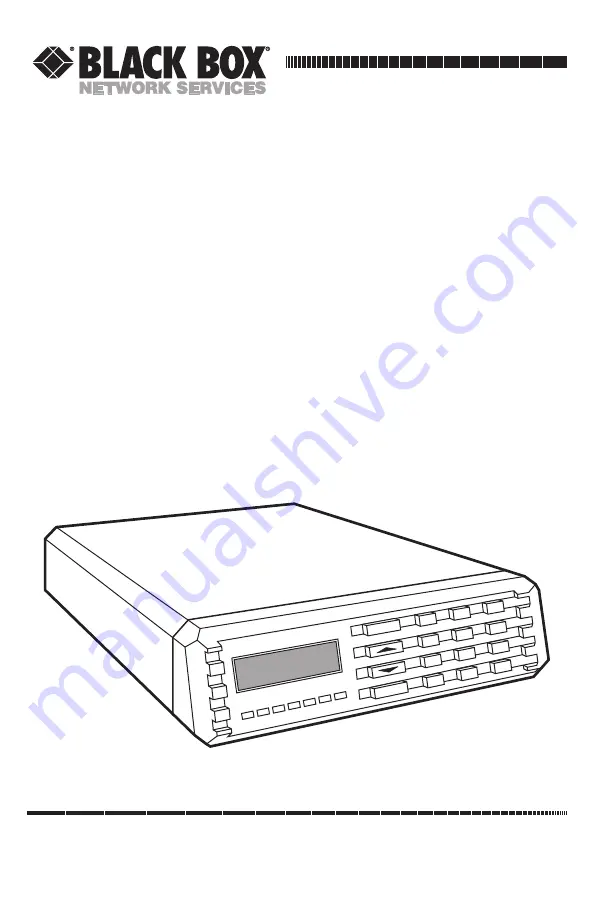
Page 9: ...change carriers In SW56 mode the CSU DSU MS DBU supports DTE rates of 2 4 4 8 9 6 19 2 38 4 asynchronous or synchronous and 56 Kbps synchronous The additional DTE rate of 57 6 Kbps is available in async modes 2 4 The Front Panel Fig 2 1 CSU DSU MS DBU Front View The Light Emitting Diodes LEDs are identified as follows RS Request to Send CS Clear to Send TD Transmit Data RD Receive Data CD Carrier ...

Page 10: ... and network connections are listed in Chapter 3 Fig 2 2 CSU DSU SW56 Rear Panel Table 2 1 Key to Fig 2 2 Item Function 1 Auxiliary EIA 232 Secondary channel services 2 Power Switch Used to turn power on or off 3 Line 1 Connection to the dedicated circuit 4 Line 2 Connection to switched backup 5 Primary EIA 232 DTE interface 6 Primary V 35 High speed digital data service 7 115 VAC Connection Power...

Page 11: ...de You must provide the following items DTE cable s An RS 232 interface cable with standard DB25 male connectors Cannon or Cinch DB 19604 432 or V 35 cable Each CSU DSU MS DBU is provided with a captive eight foot power cord terminated by a three prong plug that connects to a grounded power receptacle A telco connector is provided for interface to the network and two others provide connection to t...

Page 12: ...R1 Receive Data from network to CSU DSU Ring 1 The s LINE 2 connector is used for connection to the switched backup network The pinout for the LINE 2 connector is shown in Table 3 2 Table 3 2 Pin Assignments for the LINE 2 Connector Pin Name Description 1 R Transmit Data from CSU DSU to network ring 2 T Transmit Data from CSU DSU to network tip 3 6 Not Used 7 T1 Receive Data from network to CSU DS...

Page 13: ...onnectors are listed in Tables 3 3 and 3 4 The V 35 connector is recommended for use with data rates above 19 2 Kbps The RS 232 connector will work at up to 56 Kbps with a low capacitance cable or with the external transmit clock option selected The primary DTE rate is configured from the front panel The primary Data Terminal Equipment can operate in asynchronous or synchronous mode CAUTION To pre...

Page 14: ...ive Data RD 4 CA Request to Send RS 5 CB Clear to Send CS 6 CC Data Set Ready SR 7 AB Signal Ground SG 8 CF Received Line Signal Detector CD 9 12 Test Point 10 12 Test Point 15 DB Transmit Clock TC 17 DD Receive Clock RC 18 Local Loopback LL 20 CD Data Terminal Ready TR 21 Remote Loopback RL 22 CE Ring Indicator RI 24 DA External TX Clock ETC 25 Test Indicator TI ...

Page 15: ... Terminal Ready DTR J Ring Indicator RI L Local Loopback LL N Remote Loopback RL R 104 Received Data RD A T 104 Received Data RD B V 115 Receiver Signal Element Timing SCR A X 115 Receiver Signal Element Timing SCR B P 103 Transmitted Data SD A S 103 Transmitted Data SD B Y 114 Transmitter Signal Element Timing SCT A AA 114 Transmitter Signal Element Timing SCT B U 113 External TX Signal Element S...

Page 16: ...connector The pinout for the connector is listed in Table 3 5 Table 3 5 Pin Assignments for Auxiliary RS 232 Connector Pin EIA Description 1 AA Protective Ground PG 2 BA Transmit Data SD 3 BB Receive Data RD 4 CA Request to Send RS 5 CB Clear to Send CS 6 CC Data Set Ready SR 7 AB Signal Ground SG 8 CF Received Line Signal Detector CD on all the time ...

Page 17: ...t is stored in the non volatile configuration memory The CSU DSU MS DBU is then configured with that profile every time power is turned on or the unit is reset The CSU DSU MS DBU provides four different methods for local configuration and three different methods for remote configuration 1 Front panel 2 AT commands 3 V 25 bis 4 Remote commands 3 5 1 FRONT PANEL The front panel provides access to al...

Page 18: ...nd line can be terminated at any time by transmitting the CTRL X ASCII 018 after the AT attention code The CSU DSU MS DBU will ignore this command line and issue an OK response The command line may contain a single command or a series of commands after the AT attention code When a series of commands is used the individual commands may be separated with spaces for readability The maximum length for...

Page 19: ... to follow while the 13H in the control field indicates the final frame Bisync Option CHARACTER FORMAT 1 Data bits 7 2 Parity bit ODD COMMAND STRUCTURE SYN SYN STX V 25 bis COMMAND ETX Asynchronous Option CHARACTER FORMAT 1 Start bit 1 2 Data bits 7 3 Parity bit EVEN 4 Stop bit 1 COMMAND STRUCTURE V 25 bis COMMAND CR LF Command Descriptions The V 25 bis command set is a subset of the CCITT V 25 bi...

Page 20: ...mand processed INV An Invalid command detected CFIET Call failed on switched network busy detected CFIDE Call failed on switched network no wink detected CFINS Call failed no dial string in specified register INVCU Unknown command detected INVPS Invalid parameter syntax INVPV Invalid parameter value INVBL Invalid local password INVBM Invalid remote password INC Incoming call CNX Call connected NOT...

Page 21: ...sword may or may not be required depending on the present configuration of the unit Responses to CNL commands are returned in the data format currently configured Possible responses VALA and INVAn CNR Remote Configuration This command is used to pass AT commands over the network to the remote CSU DSU MS DBU via the V 25 bis command processor This allows a remote CSU DSU MS DBU to be configured fro...

Page 22: ...L CNX CFIxx DIC Disregard Incoming Call This command causes the V 25 bis processor to return to command mode even if there is an incoming call pending This allows the user to issue local commands and ignore the incoming calls There are no parameters associated with this command The only possible response is VAL PRN PRogram Number This command stores the supplied number into the specified register ...

Page 23: ...red numbers This list is followed by the VAL response 3 5 4 REMOTE COMMAND Remote configuration is available by attaching a remote device via the primary EIA 232 connection on the rear panel and setting the CSU DSU MS DBU to accept remote configurations The 3 CONFIG menu is used to enable or disable the CSU DSU MS DBU remote configuration capability See Chapter 4 Menu 3 CONFIG ...

Page 24: ...R Selects active menu items 3 Numeric Keypad Numbers alpha characters activate menu items Shift The alpha characters are entered by pressing the shift key Quick Quick return to the 3 main menu choices 4 CANCEL Exits submenus 5 Up and Down Changes display of menu items Scroll Arrows CSU DSU MS DBU RS CS TD RD CD ALM TST SHIFT D A E B QUICK F C 7 4 1 ENTER CANCEL 8 5 2 9 6 3 0 1 2 4 3 5 ...

Page 25: ...sired menu item is displayed press the number of the item to activate it That item will start flashing 3 When the desired menu item is flashing press the Enter button to select 4 You have invoked a submenu or set a configuration parameter The display of command accepted indicates a valid operation Cancel This button cancels the current activity and returns to the previous menu Repeat until the des...

Page 26: ...rom the beginning To view submenu items in a reverse pattern 1 When the menu is selected and the submenu items are displayed press the Up Scroll button 2 When the beginning of the list is reached pressing the up scroll button again continues the display of the same menu from the end Numeric Keypad Numbers 0 through 9 and alpha characters A through F are used for activating menu items Numbers 0 thr...

Page 27: ...isplay all relevant information for the network and DTE interfaces Displays current operating data mode loop status DTE data rate and format and DTE interface lead status The system will return to the status display when idle 2 TEST Used to control local and remote testing Selects local or remote testing defines unit address for remote testing and selects type of test and test pattern when require...

Page 28: ...ough selections in reverse order Select Press the Enter button to select the activated menu item which in turn may offer further choices If the activated item is a parameter choice it will be entered into the system The message Command Accepted is displayed briefly before returning to the currently active menu submenu item Abort To abort any operation press the Cancel button or the Quick button Th...

Page 29: ...ess the number 3 to activate 3 CONFIG That item will begin flashing 2 When the menu 3 CONFIG is flashing press the Enter button Two lines of submenu items will appear 1 LOCAL 2 REMOTE Fig 4 4 Submenu of the Main Menu 1 Press the number 1 to activate the submenu 1 LOCAL That item will begin flashing 2 Press Enter to select the activated submenu and two lines of submenu items will be displayed 1 NET...

Page 30: ...ber 1 to activate the submenu TEST TIMEOUT and the system prompts you to enter the desired parameters ENTER TIMEOUT 0 OFF 1 SEC Fig 4 8 Enter Timeout 1 Use the number keys to enter the number of seconds desired for the timeout 2 Press Enter to configure this system parameter 3 The system responds with an acceptance or rejection of the command and returns to the previous submenu If the system rejec...

Page 31: ...rational status of the network and the DTE interfaces After 30 seconds of no front panel operation on the CSU DSU SW56 it automatically reverts to the status display Fig 4 9 Operational Status Display TR OFF LOOP 56K DTE 56KSYNC DATA MODE LOOP IS NORMAL SR ON LLB OFF RLB OFF 1 STATUS DBU STATUS IDLE ...

Page 32: ...ed To exit the Status menu press the Cancel key 4 6 2 TEST The CSU DSU MS DBU is able to perform a variety of tests that allow problems in specific components of the communications circuit to be isolated and identified These various test modes for the CSU DSU MS DBU are initiated and terminated from either the front panel or the DTE interface When operating in asynchronous mode AT commands can be ...

Page 33: ...TRN 3 6 STRESS PTRN 4 1 EXIT TEST 2 DISPLAY STATUS 5 TEST PATTERN 1 2047 PATTERN 2 511 PATTERN 3 STRESS PTRN 1 4 STRESS PTRN 2 5 STRESS PTRN 3 6 STRESS PTRN 4 1 EXIT TEST 2 DISPLAY STATUS 6 SELF TEST SELF TEST CHECKSUM XXXX SELF TEST PASS 2 REMOTE UNIT 1 LOCAL UNIT ENTER TEST UNIT ADDRESS 00 1 2047 PATTERN 2 511 PATTERN 3 STRESS PTRN 1 4 STRESS PTRN 2 5 STRESS PTRN 3 6 STRESS PTRN 4 7 DATA FROM DT...

Page 34: ...3 6 STRESS PTRN 4 5 TEST PATTERN 1 2047 PATTERN 2 511 PATTERN 3 STRESS PTRN 1 4 STRESS PTRN 2 5 STRESS PTRN 3 6 STRESS PTRN 4 6 SELF TEST SELF TEST CHECKSUM XXXX SELF TEST PASS 1 LOCAL UNIT LOCAL DTE LOOP UNIT IN TEST LOOP IS NORMAL TR OFF LOOP 56K DTE 56K SYNC SR OFF LLB OFF RLB OFF DTE TEST UNIT IN TEST LOOP IS NORMAL TR OFF LOOP 56K DTE 56K SYNC SR OFF LLB OFF RLB OFF UNIT IN TEST LOOP IS NORMA...

Page 35: ...2 TEST is flashing press the Enter button The first two submenu items are displayed 1 LOCAL UNIT 2 REMOTE UNIT Fig 4 12 Local and Remote Unit Options 1 Use the number 1 key to activate the 1 Local Unit Test submenu 2 Press the Enter key to enter the submenu 3 Two of the submenu choices are displayed ...

Page 36: ...d the signal paths for this test is shown in Fig A 1 in Appendix A When the LL lead from the DTE is activated the test described above is also performed by the CSU DSU MS DBU The CSU DSU MS DBU acknowledges this DTE activated test by activating the TM on the DTE interface This particular test permits the separate sections of the CSU DSU MS DBU to be checked First it allows the local DTE interface ...

Page 37: ...Follow standard operating procedures When 1 DTE LOOP LL is flashing press the Enter button to initiate the test The system briefly displays Please Wait after which it displays the type of test being performed 1 DTE LOOP LL LOCAL DTE LOOP UNIT IN TEST LOOP IS NORMAL TR OFF LOOP 56K DTE 56K SYNC SR OFF LLB OFF RLB OFF ...

Page 38: ...t RLB Remote Loopback Input OFF ON State of the respective leads displayed immediately above Unit in Test Operating mode at CSU DSU MS DBU Loop is Normal Status of network service To Exit a Test 1 Press the Quick key to access the 1 EXIT TEST 2 DISPLAY STATUS submenu or Press the Cancel key to change from the status display to the main menu The TEST selection is active flashing 2 Press the Enter k...

Page 39: ... illustrating the loopback point and the signal paths for this test is shown in Fig A 2 in Appendix A This test allows the loop interface and a major portion of the DTE interface for the local CSU DSU MS DBU to be tested from the remote site over the actual communications circuit Like the DTE and LOOP LL test the test from the remote site is usually done with a BERT tester While this test is being...

Page 40: ...ng press the Enter button The system briefly displays Please Wait after which it displays the first of the test results 2 Continue with operational procedures described for DTE LOOP LL The next six selections are the same as for DTE Loop LL Local Loop RT Type of test being performed LOOP 56K DTE 56K SYNC 2 LOOP ONLY RT LOCAL LOOP RT UNIT IN TEST LOOP IS NORMAL TR OFF SR OFF LLB OFF RLB OFF ...

Page 41: ...ting the loopback point and the signal paths for this test is shown in Fig A 3 in Appendix A Test patterns from an external BERT tester are routed through the DTE interface section of the CSU DSU MS DBU and then to the output of the loop transmitter section where the signal is encoded for transmission Instead of being coupled onto the physical transmit circuit of the network the output of the loop...

Page 42: ...ing press the Enter button The system briefly displays Please Wait after which it displays the first of the test results 2 Continue with operational procedures described for DTE LOOP LL DTE ONLY Type of test being performed The remaining six selections are the same as for DTE LOOP LL 3 DTE ONLY DTE TEST UNIT IN TEST LOOP IS NORMAL TR OFF LOOP 56K DTE 56K SYNC SR OFF LLB OFF RLB OFF ...

Page 43: ...rn generator and detector of the CSU DSU MS DBU operate with one of six different data patterns When DTE WITH TP test is selected the particular test pattern to be transmitted by the generator must also be selected When a selection is made the test pattern detector examines the receive data stream until synchronization to the specified pattern is achieved Once synchronized the detector continues t...

Page 44: ...ich it displays the first of the test results 1 2047 PATTERN 2 511 PATTERN Fig 4 21 2047 and 511 Patterns Continue with operational procedures described for DTE Loop LL 1 2047 Pattern Selects the 2047 Pattern 2 511 Pattern Selects the 511 Pattern 3 Stress Pattern 1 Selects DDS Stress Pattern 1 4 Stress Pattern 2 Selects DDS Stress Pattern 2 5 Stress Pattern 3 Selects DDS Stress Pattern 3 6 Stress ...

Page 45: ...uring this test the TEST ERR display can be reset to zero by pressing the 1 key To verify proper operation of this test single bit errors can be injected into the transmitted test pattern by pressing the 2 key These errors appear on the TEST ERR display 5 TEST PATTERN The TEST PATTERN selection actually converts the local CSU DSU MS DBU into a BERT tester for use in testing a remote CSU DSU MS DBU...

Page 46: ...press the Enter button The system briefly displays Please Wait after which it displays the first of the test results 2 Continue with operational procedures described for DTE Loop LL 5 TEST PATTERN 1 2047 PATTERN 2 511 PATTERN 3 STRESS PTRN 1 4 STRESS PTRN 2 5 STRESS PTRN 3 6 STRESS PTRN 4 TEST PATTERN TST ERR 00 UNIT IN TEST LOOP IS NORMAL TR OFF LOOP 56K DTE 56K SYNC SR OFF LLB OFF RLB OFF DISPLA...

Page 47: ... 6 SELF TEST The self test is designed to verify current operation of the CSU DSU MS DBU It can be performed at any time Try this test if you have any doubt about whether the CSU DSU MS DBU is working Fig 4 25 Self Test Submenu 6 SELF TEST SELF TEST CHECKSUM XXXX SELF TEST PASS ...

Page 48: ...SUM XXXX Fig 4 26 Self Test and Checksum Self Test Pass indicates no problem with the operation Self Test Checksum XXXX is the software version 4 6 2 2 REMOTE UNIT SUBMENU OF 2 TEST The Remote Unit submenu lets you put a remotely installed CSU DSU MS DBU into Loopback This also applies to CSU DSU MS DBU units installed in a multipoint network After putting the remote CSU DSU MS DBU into loopback y...

Page 49: ... 2 Use the number keys to type the address of the remote CSU DSU MS DBU 3 Press the Enter key to enter the address into the system The first of the submenu items is displayed 1 2047 PATTERN 2 511 PATTERN Fig 4 29 2047 and 511 Pattern DISPLAYS 2 REMOTE UNIT ENTER TEST UNIT ADDRESS 00 1 2047 PATTERN 2 511 PATTERN 3 STRESS PTRN 1 4 STRESS PTRN 2 5 STRESS PTRN 3 6 STRESS PTRN 4 7 DATA FROM DTE REMOTE ...

Page 50: ...tress Pattern 1 4 Stress Pattern 2 Selects DDS Stress Pattern 2 5 Stress Pattern 3 Selects DDS Stress Pattern 3 6 Stress Pattern 4 Selects DDS Stress Pattern 4 7 Data From DTE Status Displays Remote with TP Test Err 00 Local DTE Loop Type of test being performed Loop 56K Loop rate DTE 56K sync DTE rate and data type Available interface leads TR Terminal Ready Input SR Set Ready Output LLB Local Lo...

Page 51: ...turning to the Main Menu for selection 2 DISPLAY STATUS re enters test display for additional viewing When a test has been requested the system briefly displays Please Wait before presenting the first test display At any test result display follow these steps 1 Press the Quick key to access the 1 EXIT TEST 2 DISPLAY STATUS submenu or 2 Press the Cancel key to change from the status display to the ...

Page 52: ...isplay Status re enters test display for additional viewing 1 EXIT TEST 2 DISPLAY STATUS Fig 4 31 Exit Test and Display Status Options 4 7 3 CONFIG The Configuration menu consists of a group of five submenus each relating to a specific interface or function of the CSU DSU MS DBU that requires setup 1 Network Opt Network Interface Parameters 2 DTE Options DTE Interface Parameters 3 Test Options Uni...

Page 53: ...dified or one of the other profiles that more closely matches the system requirements can be loaded into current memory When a different profile is loaded or the existing profile is modified it is stored in the current non volatile configuration memory The CSU DSU MS DBU is then configured with that profile every time power is turned on or until the unit is reset Submenus of 3 CONFIG 1 LOCAL Confi...

Page 54: ... TIMEOUT 2 RDL EN DIS 3 EIA LLB EN DIS 4 EIA RLB EN DIS ENTER TIMEOUT 0 OFF 00 SEC 1 RDL IGNORED 2 RDL ACCEPTED 1 DISABLED 2 ENABLED 1 PHONE NUMBER STORED NUMBER TO EDIT 1 10 1 1 AUTOMATIC DBU 2 NUMBER TO DIAL 3 ORIGIN ANSWER 4 WHEN OOS 5 NO RX SGNL 6 NO SEAL CUR 7 AUTO RESTORE 8 REDIAL COUNTER 9 FAIL TIMER A WAIT TO REDIAL NNNNNNN 7 Choices 4 Choices 2 DBU OPTIONS 1 DISABLED 2 ENABLED 1 DBU WITH ...

Page 55: ...the Cancel button returns to the previous menu level Pressing the Cancel button repeatedly returns the system to the main menu or you can press the Quick button to return to the main menu immediately 1 Press the Enter button to enter the Configuration mode The two submenu choices 1 LOCAL 2 REMOTE are displayed 2 Use the 1 key to activate the 1 Local Menu 3 Press the Enter key to enter the Local su...

Page 56: ...ONS Offers the choices of the configuration parameters that control the loop operation of the CSU DSU MS DBU Fig 4 34 Network Opt Submenu 2 Choices 8 Choices 1 NETWORK OPT 1 LOOP RATE 2 NETWORK ADDR 3 REMOTE CONFIG 4 CLOCK SOURCE DISABLE ENABLE ...

Page 57: ...f any submenu 2 through 7 is selected the system will prompt for a selection of 1 No Second Channel 2 Second Channel If this option is presented continue the same operation to arrive at the display of Command Accepted Submenu 1 Loop Rate The Loop Rate option sets the loop operating speed The unit should be set to the rate required by the DDS service The CSU DSU MS DBU also supports subrate DTE dat...

Page 58: ...EC CH B9 2 4K with secondary channel 3 4 8K SEC CH B10 4 8K with secondary channel 4 9 6K SEC CH B11 9 6K with secondary channel 5 19 2K SEC CH B12 19 2K with secondary channel 6 38 4K SEC CH B13 38 4K with secondary channel 7 56K SEC CH B14 56K with secondary channel Submenu 2 Network Addr A two digit decimal address can be assigned to each CSU DSU MS DBU This addressing capability makes it possi...

Page 59: ...tem briefly displays Command Accepted and returns to the active NETWORK OPT menu with the Remote Config selection active Table 4 7 Remote Configuration Commands Front Panel AT Command Description 1 DISABLE P4 Disable Remote Configuration 2 ENABLE P5 Enable Remote Configuration Submenu 4 Clock Source The Clock Source options specifies the timing source for the CSU DSU MS DBU s internal circuitry Wh...

Page 60: ...tion of the DTE interface of the CSU DSU MS DBU Fig 4 36 DTE Options Submenu 4 Choices 4 Choices 2 DTE OPTIONS 1 DTE RATE 2 CONNECTOR TYPE 3 DATA FORMAT 4 DTE CMD OPTION 5 TRANSMIT CLOCK 6 CS OPTIONS 7 ANTI STREAM 8 CD OPTIONS 9 TR OPTIONS A SR OPTIONS B SECONDARY RATE 6 Choices 1 SCRAMBLER OFF 2 SCRAMBLER ON 3 DATA INVERT 1 RS 232 2 V 35 1 ASYNCHRONOUS 2 SYNCHRONOUS 1 ASYNC 9 BITS 2 ASYNC 10 BITS...

Page 61: ... menu options At the end of the options the system briefly displays Command Accepted and returns to the active menu Submenu 1 DTE Rate The DTE RATE option sets the operating speed of the DTE interface when the unit is set for 56K The CSU DSU MS DBU supports six different DTE rates over a 56K Loop 1 Use the number of the desired DTE RATE to activate the selection 2 Press Enter to select the DTE rat...

Page 62: ...ith secondary channel the network will not allow both the primary and secondary channel data to be zero simultaneously For those applications where HDLC protocol is being used the above constraint can be eliminated by selecting the DATA INVERT OPTION The constraint can also be eliminated by selecting the SCRAMBLER ON option For 64K clear channel operation there is a possibility that the DTE data s...

Page 63: ...nel connectors is used to connect to the Data Terminal Equipment Menu Map 3 CONFIG 1 LOCAL 2 DTE OPT Connector Type Operation Follow standard operating procedures 1 When 2 Connector Type is flashing press the Enter button The first of the submenu items is displayed 1 RS 232 2 V 35 Fig 4 38 RS 232 and V 35 Options ...

Page 64: ...11 Connector Type Commands Front Panel AT Command Description 1 RS 232 N A Enables the EIA 232 interface 2 V 35 N A Enables the V 35 interface Submenu 3 Data Format The Data Format option is used to select either the synchronous or the asynchronous mode of operation for the DTE interface Fig 4 39 Data Format Submenu 3 DATA FORMAT 1 ASYNCHRONOUS 2 SYNCHRONOUS 1 ASYNC 9 BITS 2 ASYNC 10 BITS 3 ASYNC ...

Page 65: ...ard operating procedures to select menu options At the end of the options the system briefly displays Command Accepted and returns to the DTE Options menu NOTE If the asynchronous option is chosen the length of the data bytes must be selected 3 Use the number of the desired submenu choice to activate the desired asynchronous format 4 Press Enter to enter the selected choice into the system The sys...

Page 66: ...ITS N A 10 bits including start stop parity 3 ASYNC 11 BITS N A 11 bits including start stop parity Submenu 4 DTE CMD Option The DTE Command option is used to enable the DTE interface for one of the three different command modes 3 CONFIG 1 LOCAL 2 DTE OPT 4 DTE CMD OPTION Operation Follow standard operating procedures When 4 DTE CMD OPTION is flashing press the Enter button The first of the submen...

Page 67: ...T commands from DTE 3 V 25 SYNC N A Enables V 25 bis SDLC commands 4 V 25 BSC ASYNC N A Enables V 25 BISYNC and ASYNC Submenu 5 Transmit Clock The Transmit Clock option is used to select the source of the clock used to transfer data from the DTE into the CSU DSU MS DBU Menu Map 3 CONFIG 1 LOCAL 2 DTE OPT 5 TRANSMIT CLOCK Operation Follow standard operating procedures When 5 TRANSMIT CLOCK is flash...

Page 68: ...onnect diagram for this application is shown in Fig B 1 The External clock option is also recommended when the EIA 232 connector is used for 56 Kbps applications A special CSU DSU SW56 cable diagram for this application is shown in Fig B 2 Using this option and special cable eliminates data errors caused by excessive delays in the DTE transmit clock receiver and transmit data driver Submenu 6 CS O...

Page 69: ... or display choices for the delay Table 4 15 CS Options Commands Front Panel AT Command Description 1 FORCED ON R0 CS always ON 2 FOLLOWS RS R1 CS state same as RS state 3 FOLLOWS CD R2 CS state same as CD state 4 FOLLOWS RS CD R3 CS state same as RS and CD state If one of the options chosen involves request to send RS select the delay from RS to CS 1 CS DELAY SHORT _D0 Short Delay from RS to CS s...

Page 70: ... a multidrop network from continuously tying up the transmit circuit back to the master CSU DSU The anti stream timer is reset to zero when RS transitions to the active state and is updated every second while RS is active When the anti stream timeout expires the CSU DSU MS DBU stops transmitting DTE data into the network but continues to accept data from it This condition exists until the DTE deac...

Page 71: ...ing procedures to select menu options At the end of the options the system briefly displays Command Accepted and returns to the DTE OPTIONS menu with the Anti Stream selection active Table 4 17 Anti Stream Commands Front Panel AT Command Description 1 TIMER OFF T0 Anti stream timer disabled 2 TIME 10 SEC T1 Timeout equals 10 seconds 3 TIME 30 SEC T2 Timeout equals 30 seconds 4 TIME 60 SEC T3 Timeo...

Page 72: ...ntrol modes for the receive line signal detector CD lead Menu Map 3 CONFIG 1 LOCAL 2 DTE OPT 8 CD OPTIONS Operation Follow standard operating procedures When 8 CD OPTIONS is flashing press the Enter button The first of the submenu items is displayed 1 FORCED ON 2 NORMAL Fig 4 45 Forced On and Normal Options ...

Page 73: ... 1 FORCED ON C0 ON all the time 2 NORMAL C1 ON only when data present on loop Submenu 9 TR Options The TR Options menu is used to select the response of the CSU DSU MS DBU to the data terminal ready TR lead Menu Map 3 CONFIG 1 LOCAL 2 DTE OPT 9 TR OPTIONS Operation Follow standard operating procedures When 9 TR OPTIONS is flashing press the Enter button The first of the submenu items is displayed ...

Page 74: ...0 Ignore the TR input 2 COMMAND SWITCH D2 Switch to Backup Dedicated Submenu A SR Options The SR Options menu is used to select the operating mode for the data set ready SR lead Menu Map 3 CONFIG 1 LOCAL 2 DTE OPT A SR OPTIONS Operation Follow standard operating procedures When A SR Options is flashing press the Enter key to enter the SR Options submenu The first of the SR Options submenu items is...

Page 75: ... test or OOS Submenu B Secondary Rate The Secondary Rate option is used to select the operating speed for the secondary channel if the secondary channel option was selected during setup of the NETWORK OPT Menu Map 3 CONFIG 1 LOCAL 2 DTE OPT B SECONDARY RATE Operation To display the SECONDARY RATE submenu of the 1 LOCAL submenu of 3 CONFIG 1 Use the scroll buttons to display the B SECONDARY RATE it...

Page 76: ... Commands Front Panel AT Command Description 1 OFF _Y0 No secondary channel selected 2 75 _Y1 Secondary channel rate 75 bps 3 150 _Y2 Secondary channel rate 150 bps 4 300 _Y3 Secondary channel rate 300 bps 5 600 _Y4 Secondary channel rate 600 bps 6 1 2K _Y5 Secondary channel rate 1200 bps 7 2 4K _Y6 Secondary channel rate 2400 bps 4 7 3 3 TEST OPTIONS The Test Options menu is used to enable or dis...

Page 77: ...ures to select menu options At the end of the options the system briefly displays Command Accepted and returns to the active menu Submenu 1 Test Timeout The Test Timeout option is used to specify the length of time a CSU DSU MS DBU remains in a test mode before an automatic return to the data mode The LCD display is shown in Fig 4 50 3 TEST OPTIONS 1 TEST TIMEOUT 2 RDL EN DIS 3 EIA LLB EN DIS 4 EI...

Page 78: ...U DSU MS DBU responds to a remote digital loopback RDL request from the far end of the circuit Table 4 22 RDL Select Commands Front Panel AT Command Description 1 RDL Ignored T5 RDL request from remote CSU DSU ignored 2 RDL Accepted T4 RDL request accepted Submenu 3 EIA LLB Select The EIA LLB Select option is used to specify whether or not the CSU DSU MS DBU responds to the local loopback LLB inpu...

Page 79: ...specify whether or not the CSU DSU MS DBU responds to the remote loopback RLB input from the DTE Table 4 24 EIA RLB Select Commands Front Panel AT Command Description 1 DISABLED _R0 EIA RLB disabled 2 ENABLED _R1 EIA RLB enabled 4 7 4 4 DIAL OPTIONS The Dial Options menu is used to store up to ten telephone numbers and define Answer operation of the CSU DSU MS DBU when it is configured for Switche...

Page 80: ...ONS 1 DISABLED 2 ENABLED 1 DBU WITH 1 2 DBU WITH 2 1 DBU ORIGINATE 2 DBU ANSWER 1 ENABLED 2 DISABLED 1 ENABLED 2 DISABLED 1 ENABLED 2 DISABLED RESTORE TIMER 0 OFF __MIN ENTER REDIAL COUNT __ AUTO DBU FAIL TIME __ WAIT TO REDIAL TIME __SEC For 2 wire 4 wire Configuration Only B NETWORK TYPE 1 AT T MIC OTHER 2 US SPRINT B ERROR CONTROL C FLOW CONTROL 1 DISABLED 2 ENABLED 1 DISABLED 2 XON XOFF 3 CTS ...

Page 81: ...ons the system briefly displays Command Accepted and returns to the active menu Submenu 1 Phone Number The CSU DSU MS DBU has storage for ten numbers of 36 digits each If a phone number is to be edited the entire number must be re entered This process overwrites the previously stored number STORE NUMBER TO EDIT 1 10 X Fig 4 52 Store Phone Number Operation Use the number key to type the number to b...

Page 82: ...BU OPTIONS is flashing press the Enter button The first of the DBU Options submenu items is displayed 1 AUTOMATIC DBU 2 NUMBER TO DIAL Fig 4 53 Automatic DBU and Number to Dial Continue with standard operating procedures to select menu options At the end of the options the system briefly displays Command Accepted and returns to the active menu or display choice 1 Automatic DBU Used to specify whet...

Page 83: ...for the unit to automatically dial The CSU DSU MS DBU will then dial automatically if the leased line fails if it is set as originate Table 4 26 Number to Dial Commands Front Panel AT Command Description 1 DBU with 1 _B0 Dial Stored 1 2 DBU with 2 _B1 Dial Stored 2 3 Origin Answer This option allows the selection of the DBU unit to originate or answer if the dedicated circuit fails One end should ...

Page 84: ... DBU to go to backup if an out of service condition is encountered Table 4 28 When OOS Commands Front Panel AT Command Description 1 Enabled _G0 DBU when OOS 2 Disabled _G1 Disabled 5 No RX Signal When enabled this option allows the CSU DSU MS DBU to go to backup when the unit detects a loss of signal Table 4 29 No RX Signal Commands Front Panel AT Command Description 1 Enabled _H0 DBU when no RX ...

Page 85: ...he CSU DSU MS DBU is in the switched backup mode before it tries to revert back to the dedicated circuit The selection is entered in minutes up to 255 RESTORE TIMER 0 OFF MIN Fig 4 54 Restore Timer 8 Redial Counter This option allows the selection of the number of times the CSU DSU MS DBU will redial the far end when going to backup The redial count which is manually entered can be up to a maximum...

Page 86: ... backup The amount of time which is manually entered can be up to a maximum of 99 seconds AUTO DBU FAIL TIME SEC Fig 4 56 Auto DBU Fail A Wait to Redial This option works in conjunction with Option 8 Redial Counter It allows the selection of the amount of time between Redial attempts The amount of time which is manually entered can be up to a maximum of 99 seconds WAIT TO REDIAL TIME SEC Fig 4 57 ...

Page 87: ...ller suppressor tone is emitted by the CSU DSU MS DBU when dialing 1 AT T MCI OTHER 2 US SPRINT Fig 4 58 Network Type 4 7 5 5 MANUAL COMMAND The Manual Command option is a short cut method for entering configuration and control commands for the CSU DSU MS DBU Operation The first display prompts the user to enter the command number COMMAND 00 Fig 4 59 Command Option ...

Page 88: ...oth the command number and the present value or setting for the command The command value can be edited or re issued with the exiting value COMMAND XX VALUE 00 Fig 4 60 Command and Value Options Use the number keys to enter the hexidecimal value Press the Enter key to complete The system briefly displays Command Accepted and returns to the active menu ...

Page 89: ...U DSU MS DBU Appendix A Test Diagrams Fig A 1 DTE and Loop Test Diagram DTE TRANSMIT INTERFACE DTE RECEIVE INTERFACE LOOP TRANSMIT INTERFACE LOOP RECEIVE INTERFACE DTE TD DTE RD LOOP TX LOOP RX DTE AND LOOP ...

Page 90: ...89 APPENDIX A Test Diagrams Fig A 2 Loop Only Test Diagram DTE TRANSMIT INTERFACE DTE RECEIVE INTERFACE LOOP TRANSMIT INTERFACE LOOP RECEIVE INTERFACE DTE TD DTE RD LOOP TX LOOP RX LOOP ONLY ...

Page 91: ...90 CSU DSU MS DBU Fig A 3 DTE Only Test Diagram DTE TRANSMIT INTERFACE DTE RECEIVE INTERFACE LOOP TRANSMIT INTERFACE LOOP RECEIVE INTERFACE DTE TD DTE RD LOOP TX LOOP RX DTE ONLY ...

Page 92: ...With Test Pattern Diagram DTE TRANSMIT INTERFACE DTE RECEIVE INTERFACE LOOP TRANSMIT INTERFACE LOOP RECEIVE INTERFACE DTE TD DTE RD LOOP TX LOOP RX DTE WITH TEST PATTERN ERROR INJECT TEST PATTERN GENERATOR ERROR CLEAR 1 TEST PATTERN GENERATOR ...

Page 93: ...Pattern Only Diagram DTE TRANSMIT INTERFACE DTE RECEIVE INTERFACE LOOP TRANSMIT INTERFACE LOOP RECEIVE INTERFACE DTE TD DTE RD LOOP TX LOOP RX TEST PATTERN ONLY ERROR INJECT TEST PATTERN GENERATOR ERROR CLEAR 1 TEST PATTERN GENERATOR ...

Page 94: ...PENDIX B Clocking Configurations Appendix B Clocking Configurations Fig B 1 CSU DSU SW56 to Modem Interconnect Diagram RC ETC RD TD DCD RTS M O D E M ETC RC TD RD RTS DCD D S U III For Multi drop requirement ...

Page 95: ...ion RS 232 CONNECTOR Pin 15 Pin 24 Pin 15 ETC SCT OPTIONS FOR EXT TX CLK CSU DSU MS DBU DTE At DTE interface RS 232 connector tie transmit clock lead SCT to external transmit clock ETC as shown This may resolve data error problems caused by signal delays at high rates CSU DSU MS DBU ...

Page 96: ...e to S Register none ATVn Result Code Form 1 ATZ Reset none AT Cn DCD Option 0 AT Dn DTR Option 0 AT Fn Restore Factory Options none AT Kn Flow Control none AT Ln Network Type 0 AT Qn DTE Data Format 0 AT Rn CS Options 0 AT Sn SR Options 0 AT Tn Test Commands 0 AT V View Current Configuration none AT Wn Store User Profile 0 AT Xn Transmit Clock 0 AT Yn Power Up User Profile 0 AT Zn x Store Phone N...

Page 97: ...x Password Verify 0 AT Rx Initiate Remote Config 0 AT Tn Anti Stream Option 0 AT_An LLB Control 0 AT_Bn DBU Number to Dial 0 AT_Cn SR Control During Test 0 AT_Dn RTS CTS Delay 0 AT_En DBU Originate Answer 0 AT_Fn Scrambler Control 0 AT_Jn Auto Answer Enable Disable 0 AT_N xx Set Network Address none AT_Pn Front Panel Enable Disable 0 AT_RR LB Enable Disable 0 AT_S xx Set Serial Number none AT_Tn S...

Page 98: ...ng or Short Code LONG LONG LONG LONG Test pattern type 2047 2047 2047 2047 EIA controlled ALB DIS DIS DIS DIS EIA controlled RLB DIS DIS DIS DIS DTE Type V 35 RS 232 RS 232 RS 232 Front panel en dis EN EN EN EN Test timeout OFF OFF OFF OFF DTE Command Set V 25 AT AT DIS CS option RS FORCED FORCED RS SR test option OFF OFF OFF OFF TR option NRML NRML NRML NRML DTR RECOG DELAY 3 3 3 3 X100ms DTR COM...

Page 99: ... RS CTS delay SHRT SHRT SHRT SHRT DTE data format SYNC ASYNC ASYNC SYNC TC Timing source INT INT INT INT TX Loop Timing LOOP LOOP LOOP LOOP AT Password Control OFF OFF OFF OFF Remote config en dis EN EN EN EN Async word length 10 10 10 10 Remote DSU Address 0 0 0 0 Network Address 0 0 0 0 ...

Page 100: ...99 NOTES ...

Page 101: ...1000 Park Drive Lawrence PA 15055 1018 724 746 5500 Fax 724 746 0746 Copyright 1993 Black Box Corporation All rights reserved ...

Reviews: